TOC
TOC
THEORY OF OPERATION
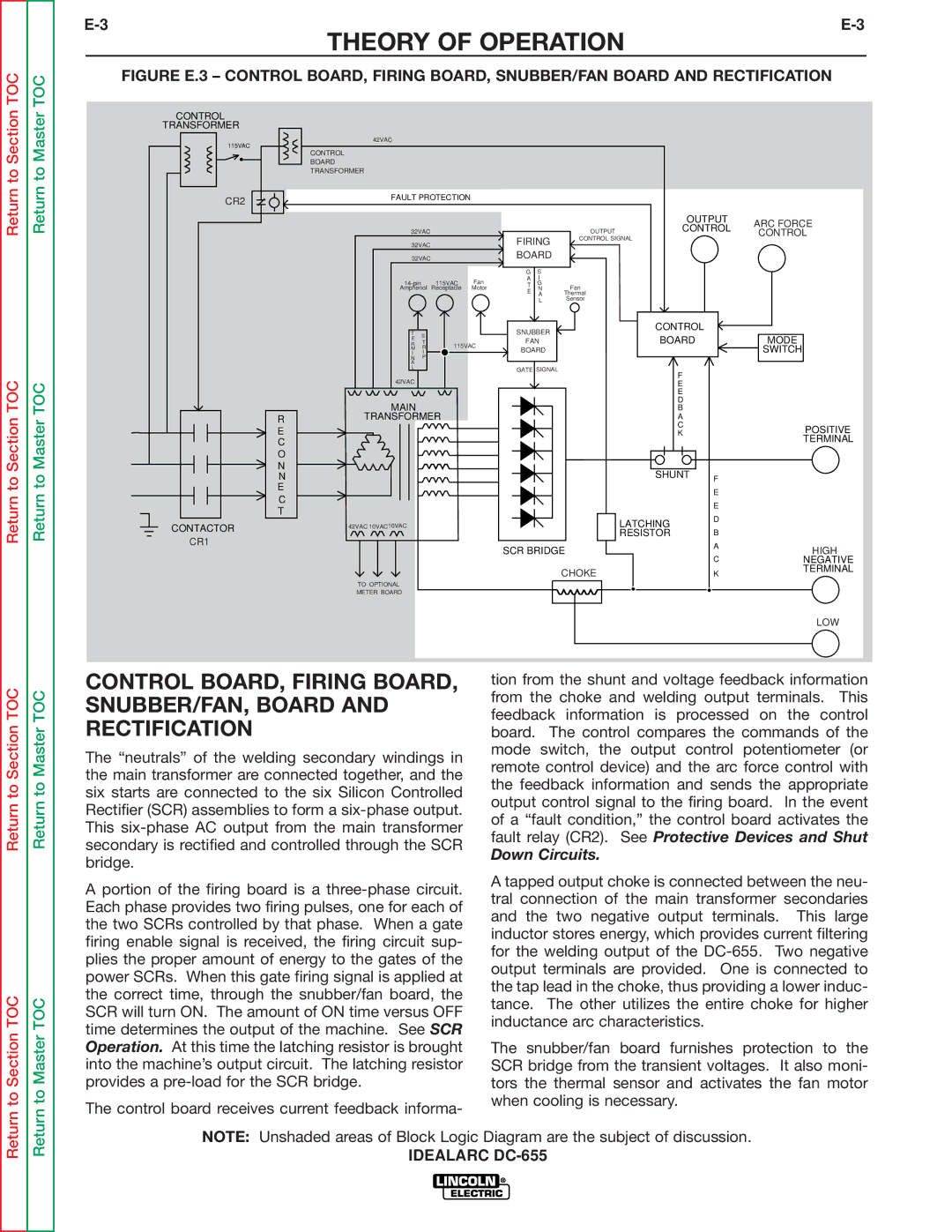
FIGURE E.3 – CONTROL BOARD, FIRING BOARD, SNUBBER/FAN BOARD AND RECTIFICATION
Return to Section
Return to Section TOC
Return to Master
Return to Master TOC
CONTROL
TRANSFORMER
115VAC
CR2
R |
E |
C |
O |
N |
N |
E |
C |
T |
CONTACTOR
CR1
42VAC
CONTROL
BOARD
TRANSFORMER
FAULT PROTECTION
|
|
|
|
|
|
| OUTPUT | ARC FORCE | |
|
|
|
|
|
|
| CONTROL | ||
32VAC |
|
|
|
| OUTPUT | CONTROL | |||
|
|
|
| FIRING | CONTROL SIGNAL |
| |||
32VAC |
|
|
|
| |||||
|
|
|
|
|
| ||||
32VAC |
|
| BOARD |
|
|
|
| ||
|
|
|
| G | S |
|
|
|
|
| 115VAC | Fan | A | I |
|
|
|
| |
| T | G |
|
|
|
| |||
Amphenol | Receptacle | Motor | N | Fan |
|
|
| ||
|
|
|
| E | A | Thermal |
|
|
|
|
|
|
|
| L | Sensor |
|
|
|
T |
|
|
| SNUBBER |
| CONTROL |
|
| |
S |
|
|
| BOARD |
| MODE | |||
R |
|
| FAN |
|
| ||||
T |
|
|
|
| |||||
E |
|
|
|
|
|
|
|
|
|
M | R | 115VAC | BOARD |
|
|
| SWITCH | ||
I | I |
|
|
|
|
| |||
N | P |
|
|
|
|
|
|
|
|
A |
|
|
|
|
|
|
|
|
|
L |
|
|
| GATE SIGNAL |
|
|
|
| |
|
|
|
|
| F |
|
| ||
42VAC |
|
|
|
|
|
|
|
| |
|
|
|
|
|
| E |
|
| |
|
|
|
|
|
|
| E |
|
|
MAIN |
|
|
|
|
|
| D |
|
|
|
|
|
|
|
| B |
|
| |
TRANSFORMER |
|
|
|
| A |
|
| ||
|
|
|
|
|
|
| C |
| POSITIVE |
|
|
|
|
|
|
| K |
| |
|
|
|
|
|
|
|
| TERMINAL | |
|
|
|
|
|
|
|
|
| |
|
|
|
|
|
|
| SHUNT | F |
|
|
|
|
|
|
|
|
|
| |
|
|
|
|
|
|
|
| E |
|
|
|
|
|
|
|
|
| E |
|
42VAC 10VAC10VAC |
|
|
|
|
|
| LATCHING | D |
|
|
|
|
|
|
|
|
| ||
|
|
|
|
|
|
| RESISTOR | B |
|
|
|
|
| SCR BRIDGE |
| A | HIGH | ||
|
|
|
|
|
| ||||
|
|
|
|
|
|
|
| C | NEGATIVE |
|
|
|
|
|
| CHOKE |
| K | TERMINAL |
|
|
|
|
|
|
|
| ||
TO OPTIONAL |
|
|
|
|
|
|
|
|
|
METER BOARD |
|
|
|
|
|
|
|
|
|
LOW
Return to Section TOC
to Section TOC
Return to Master TOC
to Master TOC
CONTROL BOARD, FIRING BOARD, SNUBBER/FAN, BOARD AND RECTIFICATION
The “neutrals” of the welding secondary windings in the main transformer are connected together, and the six starts are connected to the six Silicon Controlled Rectifier (SCR) assemblies to form a
A portion of the firing board is a
The control board receives current feedback informa-
tion from the shunt and voltage feedback information from the choke and welding output terminals. This feedback information is processed on the control board. The control compares the commands of the mode switch, the output control potentiometer (or remote control device) and the arc force control with the feedback information and sends the appropriate output control signal to the firing board. In the event of a “fault condition,” the control board activates the fault relay (CR2). See Protective Devices and Shut
Down Circuits.
A tapped output choke is connected between the neu- tral connection of the main transformer secondaries and the two negative output terminals. This large inductor stores energy, which provides current filtering for the welding output of the
The snubber/fan board furnishes protection to the SCR bridge from the transient voltages. It also moni- tors the thermal sensor and activates the fan motor when cooling is necessary.