to Section TOC
to Master TOC
TROUBLESHOOTING & REPAIR
INTERNAL TRIGGER CIRCUIT TEST (continued)
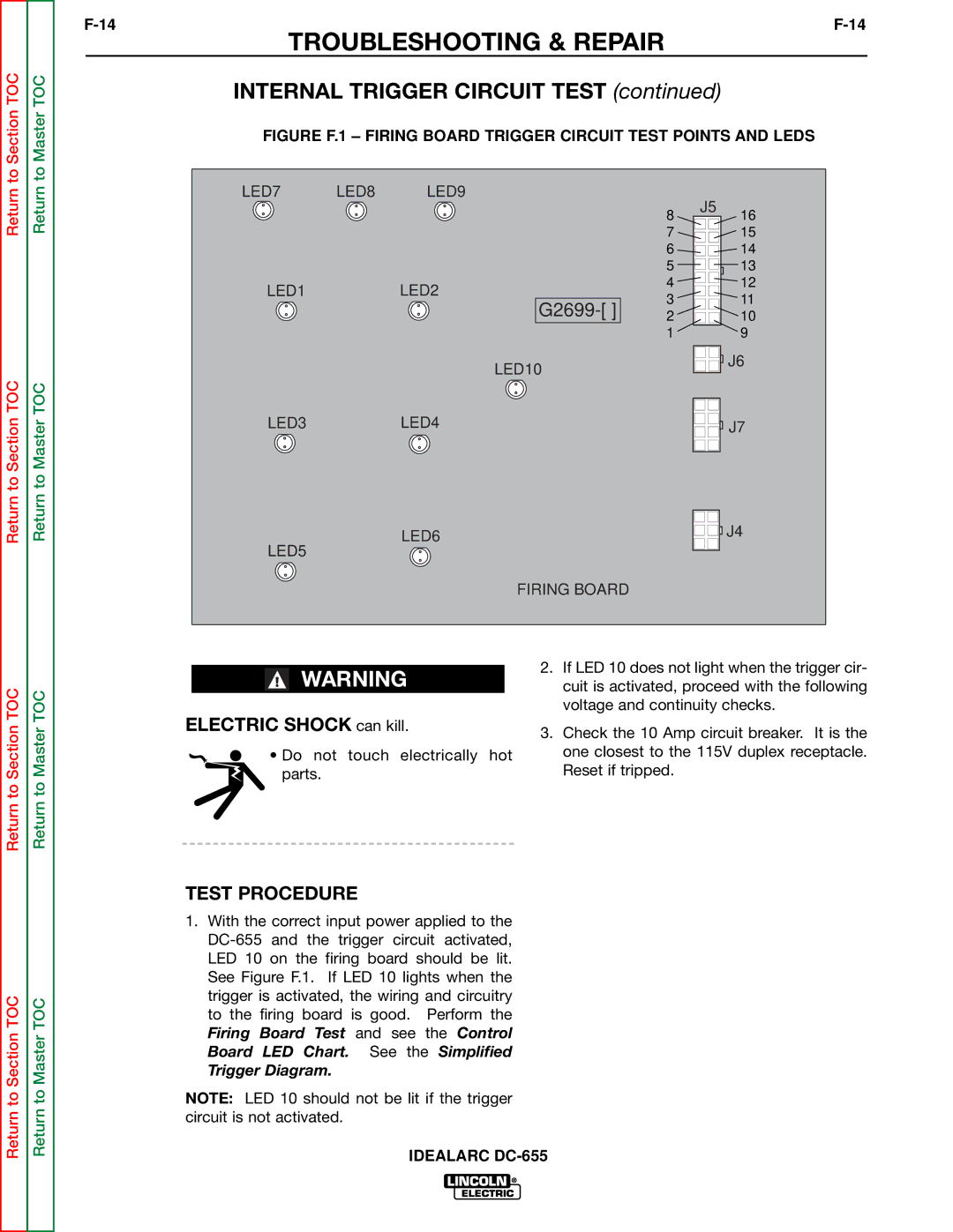
FIGURE F.1 – FIRING BOARD TRIGGER CIRCUIT TEST POINTS AND LEDS
Return
Return to Section TOC
Return
Return to Master TOC
LED7 LED8 LED9
LED1LED2
G2699-[ ]
LED10
LED3LED4
LED6
LED5
8 | J5 | 16 |
| ||
7 |
| 15 |
6 |
| 14 |
5 |
| 13 |
4 |
| 12 |
3 |
| 11 |
2 |
| 10 |
1 |
| 9 |
![]()
![]()
![]()
![]() J6
J6
J7 |
J4 |
TOC
TOC
FIRING BOARD
2. If LED 10 does not light when the trigger cir-
WARNINGcuit is activated, proceed with the following voltage and continuity checks.
Return to Section
Return to Section TOC
Return to Master
Return to Master TOC
ELECTRIC SHOCK can kill.
• Do not touch electrically hot parts.
TEST PROCEDURE
1.With the correct input power applied to the
Trigger Diagram.
NOTE: LED 10 should not be lit if the trigger circuit is not activated.
3.Check the 10 Amp circuit breaker. It is the one closest to the 115V duplex receptacle. Reset if tripped.