TROUBLESHOOTING & REPAIR
TOC | TOC |
|
|
| FIGURE F.2 – TERMINAL STRIP AND | |||||
to Section | to Master |
|
|
| ||||||
|
|
|
|
|
|
|
|
| ||
Return | Return |
|
|
|
|
|
|
|
| K=42 |
|
|
|
|
|
|
| A=32 | J=31 | ||
|
|
|
| 14 PIN MS RECEPTACLE |
|
| ||||
|
|
|
|
|
|
| B=GND | I=41 | ||
|
|
|
|
|
|
|
|
| ||
|
|
|
|
|
|
|
|
| L | N |
|
|
|
|
|
|
|
|
|
| |
|
|
|
|
|
|
|
|
| C=2 | H=21 |
|
|
|
|
|
|
|
|
|
| |
|
|
|
|
|
|
|
|
| D=4 | G=75 |
|
|
|
|
|
|
|
|
|
| |
TOC | TOC |
|
|
|
|
|
|
| E=77 | F=76 |
Section | Master |
|
|
|
|
|
|
| ||
POSITIVE |
|
|
|
| LOW INDUCTANCE | HIGH INDUCTANCE | M | |||
OUTPUT |
|
|
|
|
|
| ||||
|
|
|
|
| NEGATIVE OUTPUT |
| ||||
|
|
|
|
| NEGATIVE OUTPUT |
| ||||
TERMINAL |
|
|
|
|
| |||||
|
|
|
| TERMINAL |
| |||||
| TERMINAL STRIP |
|
| TERMINAL |
| |||||
|
|
|
|
|
| |||||
Return to | Return to |
|
|
| COVER PANEL |
|
|
|
|
|
|
|
|
|
|
|
|
|
| ||
| +21 | 4 | 2 | 31 32 | 75 | 76 | 77 |
|
| |
|
|
| TERMINAL STRIP |
|
|
TOC | TOC |
|
|
|
|
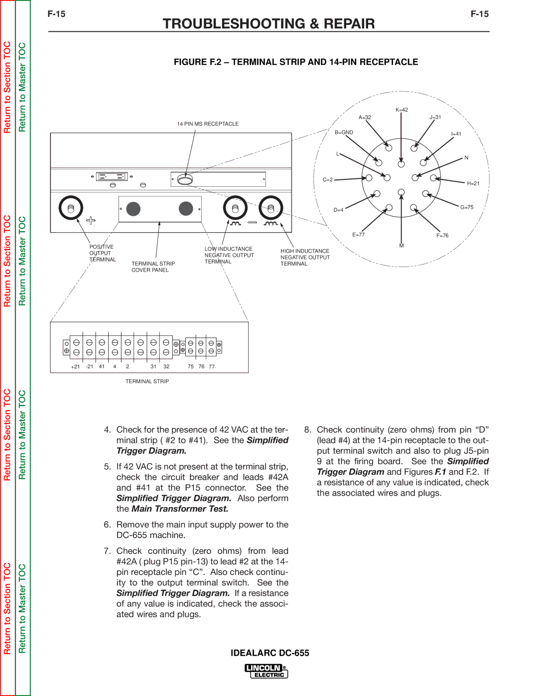
Section | Master | 4. | Check for the presence of 42 VAC at the ter- | 8. | Check continuity (zero ohms) from pin “D” |
|
| ||||
to | to |
| minal strip ( #2 to #41). See the Simplified |
| (lead #4) at the |
| Trigger Diagram. |
| put terminal switch and also to plug | ||
Return | Return |
|
| ||
| check the circuit breaker and leads #42A |
| 9 at the firing board. See the Simplified | ||
|
| 5. If 42 VAC is not present at the terminal strip, |
| Trigger Diagram and Figures F.1 and F.2. If | |
|
|
|
|
| |
|
|
| and #41 at the P15 connector. See the |
| a resistance of any value is indicated, check |
|
|
|
| the associated wires and plugs. | |
|
|
| Simplified Trigger Diagram. Also perform |
| |
|
|
|
|
| |
|
|
| the Main Transformer Test. |
|
|
|
| 6. Remove the main input supply power to the |
|
| |
|
|
|
|
| |
|
| 7. Check continuity (zero ohms) from lead |
|
| |
TOC | TOC |
| #42A ( plug P15 |
|
|
| pin receptacle pin “C”. Also check continu- |
|
| ||
|
|
|
|
| |
Section | Master |
| ity to the output terminal switch. See the |
|
|
| Simplified Trigger Diagram. If a resistance |
|
| ||
|
|
|
|
| |
|
|
| of any value is indicated, check the associ- |
|
|
Return to | Return to |
| ated wires and plugs. |
|
|
| IDEALARC |
| |||
|
|
|
| ||