Return to Section TOC
Return to Section TOC
Return to Master TOC
Return to Master TOC
ACCESSORIES
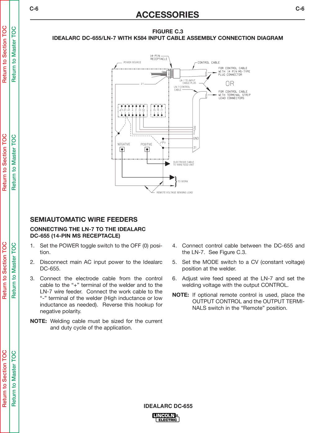
FIGURE C.3
IDEALARC DC-655/LN-7 WITH K584 INPUT CABLE ASSEMBLY CONNECTION DIAGRAM
POWER SOURCE
|
| |
21 |
| CABLE PLUG |
|
|
|
|
|
|
|
| CABLE |
+21- 21 41 | 4 | 2 | 31 32 | 75 | 76 | 77 |
|
|
|
|
|
| 32 |
|
|
|
|
|
| 31 |
|
|
|
|
|
| 2 |
|
|
|
|
|
| 4 |
|
|
|
|
|
| GND |
NEGATIVE |
|
| POSITIVE |
|
| 21 |
|
|
|
|
|
| |
|
|
|
|
|
| ELECTRODE CABLE |
|
|
|
|
|
| TO WIRE FEED UNIT |
|
|
|
|
|
| }TO WORK |
REMOTE VOLTAGE SENSING LEAD
SEMIAUTOMATIC WIRE FEEDERS
Return to Section TOC
Return to Master TOC
CONNECTING THE
1.Set the POWER toggle switch to the OFF (0) posi- tion.
2.Disconnect main AC input power to the Idealarc
3.Connect the electrode cable from the control cable to the “+” terminal of the welder and to the
NOTE: Welding cable must be sized for the current and duty cycle of the application.
4.Connect control cable between the
5.Set the MODE switch to a CV (constant voltage) position at the welder.
6.Adjust wire feed speed at the
NOTE: If optional remote control is used, place the OUTPUT CONTROL and the OUTPUT TERMI- NALS switch in the “Remote” position.
Return to Section TOC
Return to Master TOC
IDEALARC