ACCESSORIES
Return to Section TOC
Return to Section TOC
Return to Master TOC
Return to Master TOC
CONNECTING THE
1.Set the POWER toggle switch to the OFF (0) posi- tion.
2.Disconnect main AC input power to the Idealarc
3.Connect the electrode cable from the
Figure C.4.
NOTE: Welding cable must be sized for the current and duty cycle of the application.
4.Connect the control cable between the
5.Set the MODE switch to a CV (constant voltage) position.
6.Adjust wire feed speed at the
Place the OUTPUT CONTROL switch in the “Remote” position and the OUTPUT TERMINALS switch in the “Remote” position.
CONNECTING THE
1.Set the POWER toggle switch to the OFF (0) posi- tion.
2.Disconnect main AC input power to the Idealarc
3.Connect the electrode cable from the
NOTE: Welding cable must be sized for the current and duty cycle of the application.
4.Connect the
5.Set the MODE switch to a CV (constant voltage) position.
6.Adjust wire feed speed at the
7.Set the DIP switches on the
Place the OUTPUT CONTROL switch in the “Remote” position and the OUTPUT TERMINALS switch in the “Remote” position.
Return to Section TOC
Return to Section TOC
Return to Master TOC
Return to Master TOC
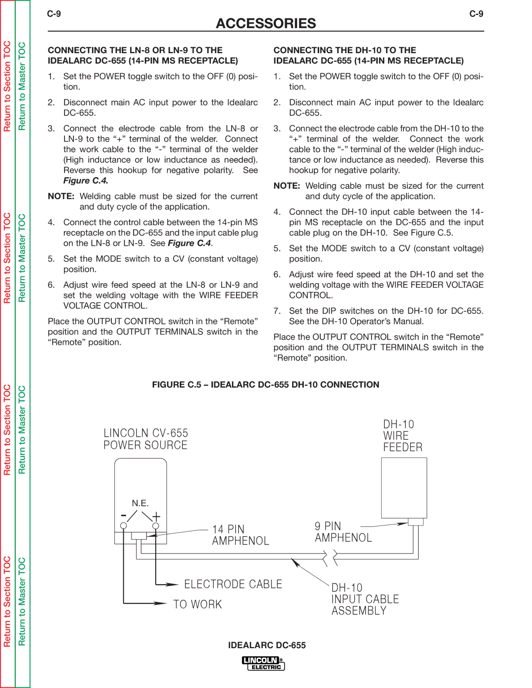
FIGURE C.5 – IDEALARC DC-655 DH-10 CONNECTION
LINCOLN | |
WIRE | |
POWER SOURCE | FEEDER |
- N.E. + | 9 PIN | |
14 PIN | ||
AMPHENOL | AMPHENOL | |
ELECTRODE CABLE | ||
TO WORK | INPUT CABLE | |
ASSEMBLY | ||
|
IDEALARC