INSTALLATION
Return to Section TOC
INPUT POWER SUPPLY CONNECTIONS
A qualified electrician should connect the input power supply leads.
1.Follow all national and local electrical codes.
2.Use a
3.Remove the input access door at upper rear of the machine.
RECONNECT PROCEDURE
WARNING
Electric Shock Can Kill
•Disconnect input power before per- forming this procedure.
Return to Section TOC
Section TOC
Return to Master TOC
Return to Master TOC
Master TOC
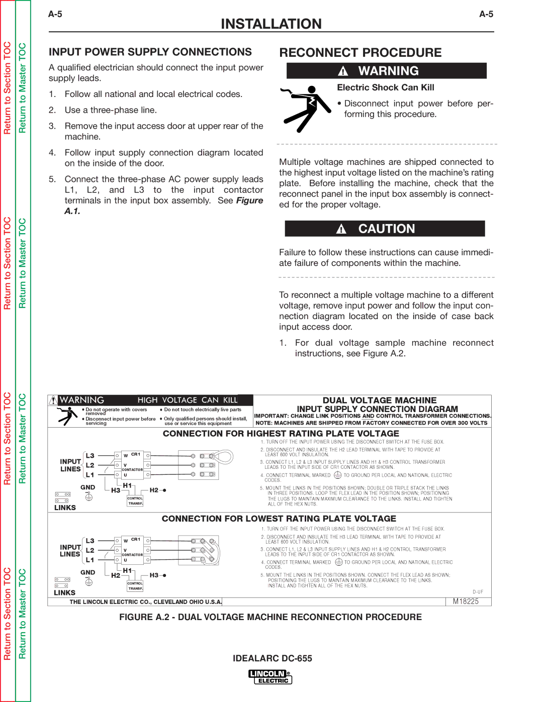
4. Follow input supply connection diagram located | Multiple voltage machines are shipped connected to | |
on the inside of the door. | ||
5. Connect the | the highest input voltage listed on the machine’s rating | |
plate. Before installing the machine, check that the | ||
L1, L2, and L3 to the input contactor | ||
reconnect panel in the input box assembly is connect- | ||
terminals in the input box assembly. See Figure | ||
ed for the proper voltage. | ||
A.1. | ||
| ||
| CAUTION | |
| Failure to follow these instructions can cause immedi- | |
| ate failure of components within the machine. | |
| To reconnect a multiple voltage machine to a different | |
| voltage, remove input power and follow the input con- | |
| nection diagram located on the inside of case back | |
| input access door. | |
| 1. For dual voltage sample machine reconnect | |
| instructions, see Figure A.2. |
|
| DUAL VOLTAGE MACHINE |
Do not operate with covers | Do not touch electrically live parts | INPUT SUPPLY CONNECTION DIAGRAM |
removed | Only qualified persons should install, | IMPORTANT: CHANGE LINK POSITIONS AND CONTROL TRANSFORMER CONNECTIONS. |
Disconnect input power before | ||
servicing | use or service this equipment | NOTE: MACHINES ARE SHIPPED FROM FACTORY CONNECTED FOR OVER 300 VOLTS |
Return to
Return to
L3 | W CR1 | |
INPUT | V | |
LINES L2 | ||
CONTACTOR | ||
L1 | U | |
GND | H1 | |
| H3 | |
| CONTROL | |
| TRANSF. |
LINKS
CONNECTION FOR HIGHEST RATING PLATE VOLTAGE
| 1 | . TURN OFF THE INPUT POWER USING THE DISCONNECT SWITCH AT THE FUSE BOX. | |
| 2 | . DISCONNECT AND INSULATE THE H2 LEAD TERMINAL WITH TAPE TO PROVIDE AT | |
|
| LEAST 600 VOLT INSULATION. |
|
| 3. CONNECT L1, L2 & L3 INPUT SUPPLY LINES AND H1 & H3 CONTROL TRANSFORMER | ||
|
| LEADS TO THE INPUT SIDE OF CR1 CONTACTOR AS SHOWN. | |
| 4 | . CONNECT TERMINAL MARKED | TO GROUND PER LOCAL AND NATIONAL ELECTRIC |
|
| CODES. |
|
H2 | 5. MOUNT THE LINKS IN THE POSITIONS SHOWN; DOUBLE OR TRIPLE STACK THE LINKS | ||
|
| IN THREE POSITIONS. LOOP THE FLEX LEAD IN THE POSITION SHOWN; POSITIONING | |
THE LUGS TO MAINTAIN MAXIMUM CLEARANCE TO THE LINKS. INSTALL AND TIGHTEN
ALL OF THE HEX NUTS.
Return to Section TOC
Return to Master TOC
|
|
|
| CONNECTION FOR LOWEST RATING PLATE VOLTAGE | ||
|
|
|
|
| 1. TURN OFF THE INPUT POWER USING THE DISCONNECT SWITCH AT THE FUSE BOX. | |
|
| L3 |
| W CR1 | 2. DISCONNECT AND INSULATE THE H3 LEAD TERMINAL WITH TAPE TO PROVIDE AT | |
INPUT |
| LEAST 600 VOLT INSULATION. |
| |||
L2 |
| V | 3. CONNECT L1, L2 & L3 INPUT SUPPLY LINES AND H1 & H2 CONTROL TRANSFORMER | |||
LINES |
|
| CONTACTOR | LEADS TO THE INPUT SIDE OF CR1 CONTACTOR AS SHOWN. | ||
|
| L1 |
| U | 4. CONNECT TERMINAL MARKED | TO GROUND PER LOCAL AND NATIONAL ELECTRIC |
| GND |
| H1 | CODES. |
| |
| H2 | 5. MOUNT THE LINKS IN THE POSITIONS SHOWN. CONNECT THE FLEX LEAD AS SHOWN; | ||||
|
|
| H3 | |||
|
|
|
| CONTROL | POSITIONING THE LUGS TO MAINTAIN MAXIMUM CLEARANCE TO THE LINKS. | |
|
|
|
| INSTALL AND TIGHTEN ALL OF THE HEX NUTS. | ||
|
|
|
| TRANSF. | ||
LINKS |
|
|
|
| ||
|
|
|
|
| ||
THE LINCOLN ELECTRIC CO., CLEVELAND OHIO U.S.A. |
| M18225 | ||||