Return to Section TOC
Return to Section TOC
Return to Section TOC
Return to Section TOC
Return to Master TOC
Return to Master TOC
Return to Master TOC
Return to Master TOC
|
| TROUBLESHOOTING & REPAIR |
|
| Observe Safety Guidelines | TROUBLESHOOTING GUIDE | |
detailed in the beginning of this manual.
PROBLEMS | POSSIBLE AREAS OF | RECOMMENDED |
| |||||
(SYMPTOMS) | MISADJUSTMENT(S) | COURSE OF ACTION | ||||||
|
|
|
|
|
| |||
|
| WELDING PROBLEMS |
|
|
| |||
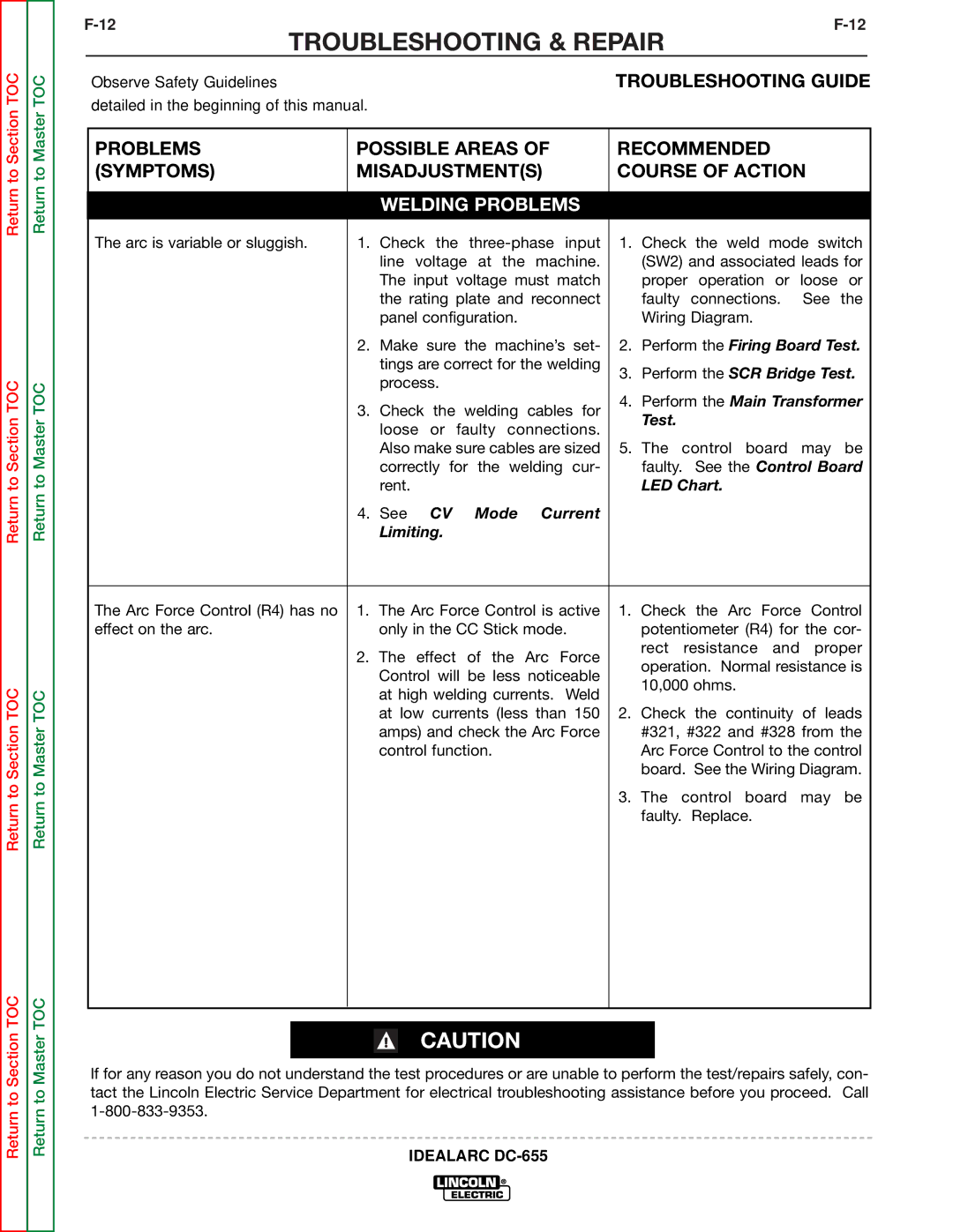
The arc is variable or sluggish. | 1. | Check the | 1. Check the weld mode switch | |||||
|
| line voltage at the machine. | (SW2) and associated leads for | |||||
|
| The input voltage must match | proper operation or loose or | |||||
|
| the rating plate and reconnect | faulty | connections. | See the | |||
|
| panel configuration. |
| Wiring Diagram. |
| |||
| 2. Make | sure | the machine’s set- | 2. Perform the Firing Board Test. | ||||
|
| tings are correct for the welding | 3. Perform the SCR Bridge Test. | |||||
|
| process. |
|
| ||||
|
|
|
|
|
|
| ||
| 3. | Check | the | welding | cables for | 4. Perform the Main Transformer | ||
| Test. |
|
| |||||
|
| loose | or | faulty connections. |
|
| ||
|
|
|
|
| ||||
|
| Also make sure cables are sized | 5. The control board may be | |||||
|
| correctly for the welding cur- | faulty. | See the Control Board | ||||
|
| rent. |
|
|
| LED Chart. |
| |
| 4. | See | CV | Mode | Current |
|
|
|
|
| Limiting. |
|
|
|
|
| |
|
|
|
| |||||
The Arc Force Control (R4) has no | 1. | The Arc Force Control is active | 1. Check the Arc Force Control | |||||
effect on the arc. |
| only in the CC Stick mode. | potentiometer (R4) for the cor- | |||||
| 2. | The effect | of the | Arc Force | rect | resistance and | proper | |
| operation. Normal resistance is | |||||||
|
| Control will be less noticeable | ||||||
|
| 10,000 ohms. |
| |||||
|
| at high welding currents. Weld |
| |||||
|
|
|
|
| ||||
|
| at low currents (less than 150 | 2. Check the continuity of leads | |||||
|
| amps) and check the Arc Force | #321, #322 and #328 from the | |||||
|
| control function. |
| Arc Force Control to the control | ||||
|
|
|
|
|
| board. See the Wiring Diagram. | ||
|
|
|
|
|
| 3. The control board may be | ||
|
|
|
|
|
| faulty. Replace. |
| |
|
|
|
|
|
|
|
|
|
CAUTION
If for any reason you do not understand the test procedures or are unable to perform the test/repairs safely, con- tact the Lincoln Electric Service Department for electrical troubleshooting assistance before you proceed. Call
