Return to Section TOC
Return to Section TOC
Return to Master TOC
Return to Master TOC
OPERATION
CONTROLS AND SETTINGS
All operator controls and adjustments are located on the case front of the
8 | 2 | 9 |
| 3 |
|
1

DC-655
7 | 4 | 5 | 6 |
|
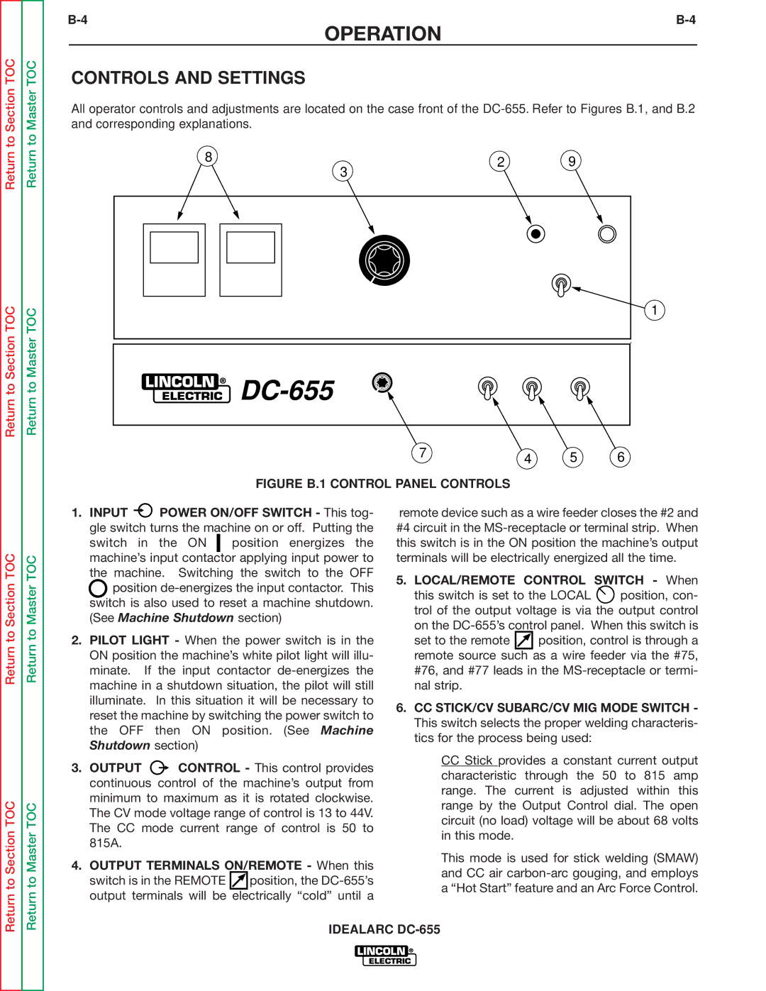
FIGURE B.1 CONTROL PANEL CONTROLS
Return to Section TOC
Return to Section TOC
Return to Master TOC
Return to Master TOC
1.INPUT ![]() POWER ON/OFF SWITCH - This tog- gle switch turns the machine on or off. Putting the
POWER ON/OFF SWITCH - This tog- gle switch turns the machine on or off. Putting the
switch in the ON | position energizes the |
machine’s input contactor applying input power to the machine. Switching the switch to the OFF ![]() position
position
2.PILOT LIGHT - When the power switch is in the ON position the machine’s white pilot light will illu- minate. If the input contactor
3.OUTPUT ![]() CONTROL - This control provides continuous control of the machine’s output from minimum to maximum as it is rotated clockwise. The CV mode voltage range of control is 13 to 44V. The CC mode current range of control is 50 to 815A.
CONTROL - This control provides continuous control of the machine’s output from minimum to maximum as it is rotated clockwise. The CV mode voltage range of control is 13 to 44V. The CC mode current range of control is 50 to 815A.
4.OUTPUT TERMINALS ON/REMOTE - When this switch is in the REMOTE ![]() position, the
position, the
remote device such as a wire feeder closes the #2 and #4 circuit in the
5.LOCAL/REMOTE CONTROL SWITCH - When
this switch is set to the LOCAL ![]() position, con- trol of the output voltage is via the output control
position, con- trol of the output voltage is via the output control
on the
set to the remote ![]() position, control is through a remote source such as a wire feeder via the #75, #76, and #77 leads in the
position, control is through a remote source such as a wire feeder via the #75, #76, and #77 leads in the
6.CC STICK/CV SUBARC/CV MIG MODE SWITCH - This switch selects the proper welding characteris- tics for the process being used:
CCStick provides a constant current output characteristic through the 50 to 815 amp range. The current is adjusted within this range by the Output Control dial. The open circuit (no load) voltage will be about 68 volts in this mode.
This mode is used for stick welding (SMAW) and CC air
IDEALARC