Section TOC
Master TOC
TROUBLESHOOTING & REPAIR
STATIC SCR TEST (continued)
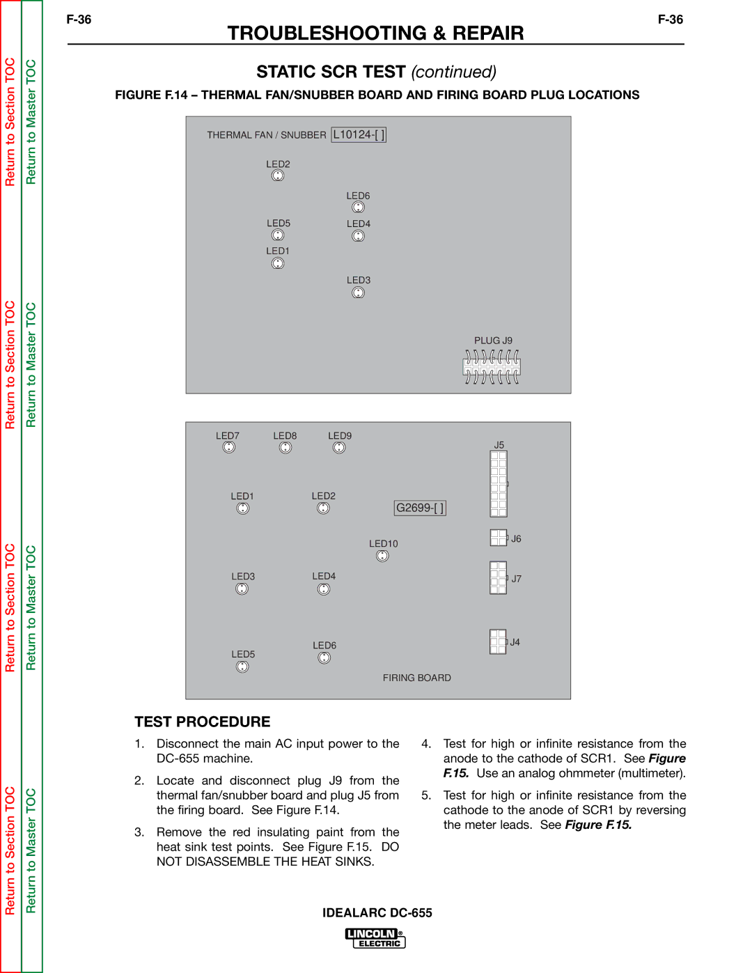
FIGURE F.14 – THERMAL FAN/SNUBBER BOARD AND FIRING BOARD PLUG LOCATIONS
Return to
Return to
THERMAL FAN / SNUBBER
LED2
LED5
LED1
LED6
LED4
LED3
Return to Section TOC
Return to Section TOC
Return to Master TOC
Return to Master TOC
PLUG J9
LED7 | LED8 | LED9 |
| J5 |
|
|
|
| |
LED1 |
| LED2 |
| |
|
|
|
| |
|
|
| LED10 | J6 |
|
|
|
| |
LED3 |
| LED4 |
| J7 |
|
| LED6 |
| J4 |
LED5 |
|
|
| |
|
|
|
| |
|
|
| FIRING BOARD |
|
TEST PROCEDURE
Return to Section TOC
Return to Master TOC
1.Disconnect the main AC input power to the
2.Locate and disconnect plug J9 from the thermal fan/snubber board and plug J5 from the firing board. See Figure F.14.
3.Remove the red insulating paint from the heat sink test points. See Figure F.15. DO NOT DISASSEMBLE THE HEAT SINKS.
4.Test for high or infinite resistance from the anode to the cathode of SCR1. See Figure F.15. Use an analog ohmmeter (multimeter).
5.Test for high or infinite resistance from the cathode to the anode of SCR1 by reversing the meter leads. See Figure F.15.