Connections
 Connecting to CCTV camera, monitor, and sensor
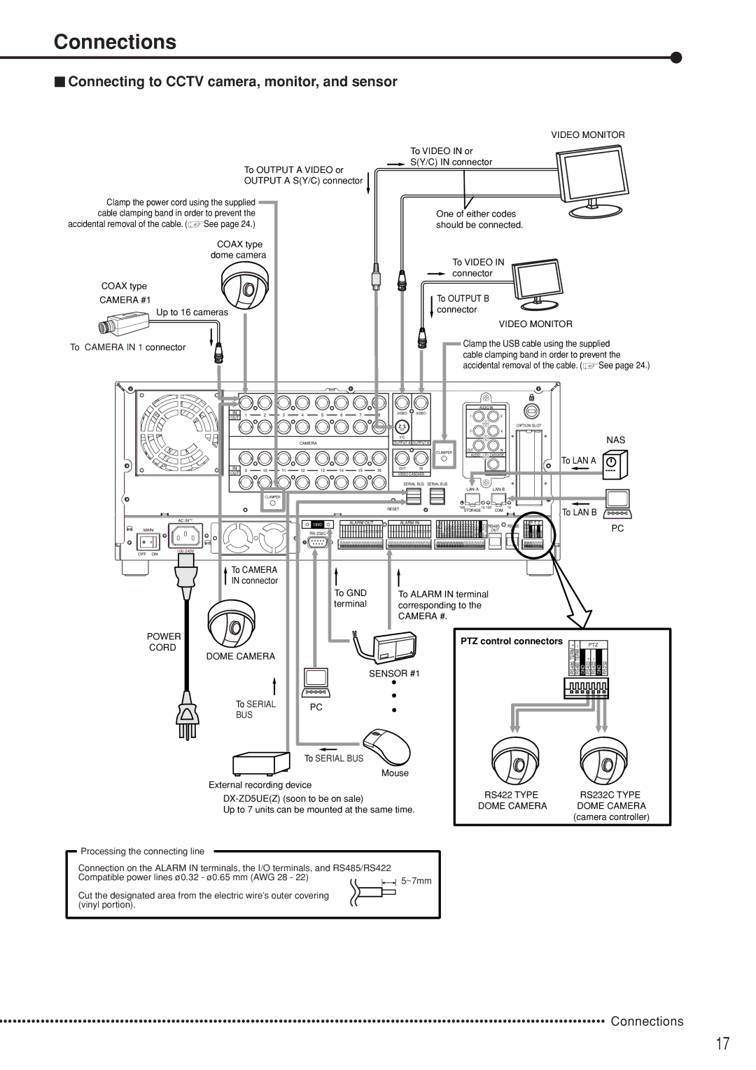
To OUTPUT A VIDEO or OUTPUT A S(Y/C) connector
VIDEO MONITOR
To VIDEO IN or
![]() S(Y/C) IN connector
S(Y/C) IN connector
Clamp the power cord using the supplied cable clamping band in order to prevent the
accidental removal of the cable. (![]() See page 24.)
See page 24.)
COAX type dome camera
COAX type
CAMERA #1
Up to 16 cameras
One of either codes should be connected.
To VIDEO IN connector
To OUTPUT B connector
VIDEO MONITOR
To CAMERA IN 1 connector
IN | 1 | 2 | 3 | 4 | 5 | 6 | 7 | |
OUT | ||||||||
|
|
|
|
|
|
| ||
|
|
|
| CAMERA |
|
|
| |
IN | 9 | 10 | 11 | 12 | 13 | 14 | 15 | |
OUT | ||||||||
|
|
|
|
|
|
| ||
|
| CLAMPER |
|
|
|
|
| |
~ |
|
|
|
|
|
|
|
8
16
VIDEO VIDEO
Y/C
OUTPUT A OUTPUT B
CLAMPER
OUT IN
VIDEO CASCADE
SERIAL BUS SERIAL BUS
RESET
Clamp the USB cable using the supplied cable clamping band in order to prevent the
accidental removal of the cable. (![]() See page 24.)
See page 24.)
AUDIO IN |
| |
1 | 2 |
|
|
| OPTION SLOT |
3 | 4 |
|
|
| NAS |
OUT | IN |
|
AUDIO | CASCADE | To LAN A |
|
| |
| AUDIO OUT |
|
| ||
100 | 10 100 | 10 |
STORAGE | COM | To LAN B |
|
| |
| AC IN | GND | ALARM OUT | |
|
| |||
MAIN |
| 1 2 3 4 5 6 7 8 9 | 10 11 12 13 | |
|
|
|
| |
14 | 15 | 16 |
|
|
|
1 2 3 4 5 6 7 8 9 10 11 12 13 14 15 16 | CLOCKADJ ADJCLOCKOUT REC STOPREC EMERGENCY RESERVED OUTMODE1 + OUTMODE1 – OUTMODE2 + OUTMODE2 – OUTMODE3 + OUTMODE3 – OUTMODE4 + OUTMODE4 – OUTCALL+ OUTCALL– | 350mAMAX 12VDCOUT |
|
|
|
|
| TERMRS485+ TERMRS485– | RS422+ RS422– | RS232 |
|
|
| ||||||||||||||||
|
|
|
| ALARM IN |
|
| RS485 |
| RS485 |
| P T Z |
|
|
| PC | ||||||||||||||
|
|
|
|
|
|
|
|
|
|
|
|
|
|
|
|
|
|
| OUT |
| IN |
|
|
|
|
|
| ||
|
|
|
|
|
|
|
|
|
|
|
|
|
|
|
|
|
|
|
|
|
|
|
|
|
|
|
|
|
|
|
|
|
|
|
|
|
|
|
|
|
|
|
|
|
|
|
|
|
|
|
|
|
|
|
|
|
|
|
|
OFF ON
![]() To CAMERA
To CAMERA
IN connector
To GND terminal
To ALARM IN terminal corresponding to the CAMERA #.
POWER
PTZ control connectors
CORD
DOME CAMERA
SENSOR #1
RS485 TERM +
RS485 TERM –
PTZ
GND +RS422
To SERIAL BUS
PC
To SERIAL BUS
Mouse
External recording device
Up to 7 units can be mounted at the same time.
RS422 TYPE | RS232C TYPE |
DOME CAMERA | DOME CAMERA |
| (camera controller) |
Processing the connecting line
Connection on the ALARM IN terminals, the I/O terminals, and RS485/RS422 Compatible power lines ø0.32 - ø0.65 mm (AWG 28 - 22)
Cut the designated area from the electric wire’s outer covering (vinyl portion).
5~7mm
•••••••••••••••••••••••••••••••••••••••••••••••••••••••••••••••••••••••••••••••••••••••••••••••••••••••••••••••••••••••••••••••••• Connections
17