Error Code List
PLC Function
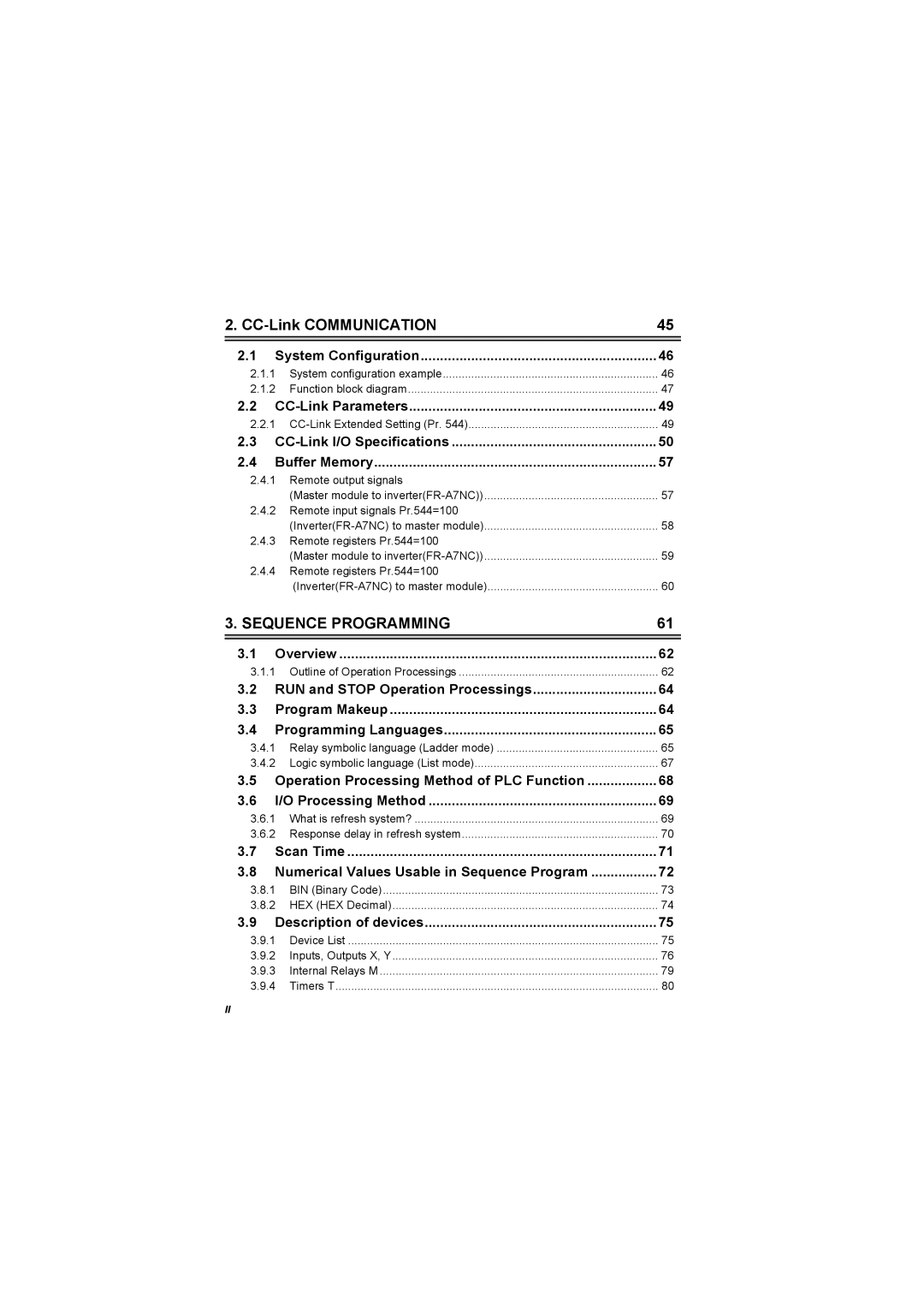
Communication Sequence Programming
Device Map
Inverter Status Monitoring, Special Registers for Control
Analog I/O function
Paluse train input function PID control
Program Makeup Programming Languages
CC-Link I/O Specifications Buffer Memory
CC-Link Parameters
Overview
Bit Device Processing Method
Counters C
Function List
Keyword Registration
171
How to Read the Error Code 172
Basic Instructions 140
155
PLC Function
Using GX Developer for RS-485 Communication
Function Block Diagram
A700 Sequence Section
PLC Function Specifications
Support GX Developer ver.8.0 or more GX Developer Setting
System Configuration
System configuration example
Communication specifications
Maker
Type
Precautions for sequence program creation
Prior to Sequence Program Creation
Usable main GX Developer functions
Sequence program execution key
Sequence program write
GX Developer Default Setting Range Usable device range
Setting list of built-in PLC function parameter
Device Map
1 I/O device map
Device Name Remarks
RAM
M0 to M63
Internal relay M device map
Data register D device map
Special relays
Device Map
Name Description
Special registers
Map
Inverter operation
Input terminal
D9205 For control D9206 Special registers D9207
PID
Unit Condition
Device Name Setting Data Example
Data that can be read at all times
Operation monitor
Data
Error No Error Name Details
Alarm definition read program example
Data read timing chart
Operation mode setting read D9140
Operation mode setting read program example
Set frequency read Eeprom program example
Set frequency RAM D9141
Set frequency RAM read program example
Set frequency Eeprom D9142
Device Name
Data write timing chart
Operation mode setting write D9143 Data are as follows
When Pr =2, switching is performed as shown below
Operation mode setting write program example
Set frequency RAM D9144
Set frequency write RAM program example
Following program changes the set frequency RAM to 30Hz
Set frequency Eeprom D9145
Set frequency write Eeprom program example
Following program changes the set frequency Eeprom to 10Hz
Alarm definition batch clear D9146
Alarm definition batch clear program example
Following program batch-clears the alarm history
Following program clears all parameters
Device No Setting Description Details
Parameter clear D9147
All parameter clear program example
Device No Name Data Access Enable Condition
Inverter operation status control
Inverter operation status control D9148
B15 B12B11 B8B7 B4B3 1 1 1 1 1 1 1 1 1 Invalid
Hffff is stored into D9150. Normal
Inverter parameter access error D9150
Inverter status D9151
Parameter
Reading the inverter parameters
Inverter Parameter Read/Write Method
Inverter parameter data read timing chart
Writing the inverter parameters
Inverter parameter data write timing chart
Range Unit
Device Inverter Initial Setting Minimum Setting
User Area Read/Write Method
User parameter read/write method
Analog output
Device Terminal Name Setting
Analog I/O function
Analog input
Selection
Parameter Name Initial Setting Description Value Range
Device No Name Setting Description Range
Paluse train input function
Setting Description Range
PID control
Parameter Name Initial Value
Device No Name Setting Description Range
Inverter Operation Lock Mode Setting
Name Initial Setting Minimum Setting Range Unit
Setting Description
Memo
Communication
System configuration example
CPU
Function block diagram
PLC CPU
Remote register function can be extended
CC-Link Extended Setting Pr
Parameter Initial Setting Name CC-Link Description Number
CC-Link Parameters
Remote I/O
CC-Link I/O Specifications
Remote resister
Data I/O image
Address Description
RAM, Eeprom
Bits
Address Description Upper
Same as when Pr = 112 Refer to
RWrn+7 Sixth monitor value RWwn+8
PLC function
Address
Remote output signals Master module to inverterFR-A7NC
Buffer Memory
Station Buffer Memory
F2H
Station Buffer
Station Buffer Memory Address
Remote registers Pr.544=100 Master module to inverterFR-A7NC
Remote registers Pr.544=100 InverterFR-A7NC to master module
Numerical Values Usable in Sequence Program
Processing Method Scan Time
Instruction Format
Operation Processing Method of PLC Function
Outline of Operation Processings
Overview
END processing
Operation Processings of Built-in PLC function
Program Makeup
RUN and Stop Operation Processings
Relay symbolic language Ladder mode
Programming Languages
Ladder Blocks
Operation Processing Sequence
Logic symbolic language
Logic symbolic language List mode
Operation Processing Method of Built-in PLC Function
Operation Processing Method of PLC Function
What is refresh system?
I/O Processing Method
Control system is a refresh system
Ladder example
Response delay in refresh system
When Y1E turns on earliest
When Y1E turns on latest
Scan Time
Decimal Code Hexadecimal Code Binary Code
Numerical Values Usable in Sequence Program
DEC Decimal Code BIN Binary Code
BIN Binary Code
HEX HEX Decimal
Device List
Description of devices
10 Inputs X, Outputs Y
Inputs, Outputs X, Y
Inputs
Outputs Y
14 Internal Relay
Internal Relays M
Timing chart
Timers T
5 100ms, 10ms and 100ms retentive timers
15 Timing Chart
16 Timing Chart
Timer processing method and accuracy
Timer timing method
18 Count Ladder
Counters C
Count processing in refresh system
19 Counter Counting Method
Counting method
Maximum counting speed of counter
Data Registers D
Special Relays, Special Registers
Special Application/Description Relay
Function Description
Function List
Refer to the GX Developer manual for details
21 Timing Chart for RUN/STOP Using Remote RUN Contact
Stop RUN/STOP
Watchdog Timer Operation clog up monitor timer
Self-diagnostic Function
CPU Status Error Definition Operation
Error-time operation mode
Keyword Registration
YES
Instruction Format
Changed during program execution
Source S
Specify the numerical value to be used for
Program creation, it is fixed and cannot be
Digit designation processing
25 Digit Designation Setting Range for 16-bit Instruction
Bit Device Processing Method
20.1 1-bit processing
27 Ladder Examples and Processingse
Decimal Notation Hexadecimal Notation
Numerical value setting method 1 Decimal number
Handling of Numerical Value
Hexadecimal number
Error processing
Operation Error
Indicates Destination Operation result
How to use the instruction list
Indicates the symbol used in the ladder diagram
Instructions List
Symbol Execution Condition
23.2 Sequence instruction
Symbol Processing
106
OR=
Basic instructions
∗ P
Application instructions
Description of the Instructions
Description
, the instructions are described in the following format
LD, LDI, AND, ANI, OR, ORI
Sequence Instructions
AND, ANI
Functions
Execution Conditions
LD, LDI
Program Examples
LD , LDI ,
ANI , or , ORI
Block a Block B
ORB
ANB
Program Examples
ANB, ORB
118
119
MPS
MRD
MPP
121
Program using MPS, MRD and MPP
Program Example
MPS , MRD , MPP
OUT Instruction Operation Result Coil Contacts
Output Instructions Bit device, timer, counter ... OUT
Outt
Outc
Contact
Program Examples
OUT
Program that outputs to the output module
Device Status
Output Instructions Device set, reset ... SET, RST
SET
RST
SET and RST instructions are executed every scan
SET , RST
Operations of SET and RST instructions
Program that resets the 100ms retentive timer and counter
Program that resets the data register contents to
Digit Flag
PLS
Program that executes the PLS instruction when X9 turns on
Program that executes the PLF instruction when X9 turns off
PLF
Shift Instructions Bit device shift ... SFT, Sftp
Program that shifts the Y7 B data when X8 turns on
Program Example
SFT
MC, MCR
Master Control Instructions Master control set, reset
134
MCR
Display in ladder mode
136
End Instruction Sequence program end ... END
NOP
Other Instructions No operation ... NOP
Contact short-circuit AND, ANI
Instruction
Symbol
Basic Instructions
Comparison Operation Instructions
141
S1 ≠ S2 S1 = S2 S1 ≤ S2
S1 = S2
S1 S2
S1 ≤ S2
Program that compares the D0 and D3 data
Program that compares the X0-F data and D3 data
Program that compares the BCD value 100 and D3 data
Program that compares the BIN value 100 and D3 data
Arithmetic Operation Instructions
145
146
Is made at the highest bit b15
Addition/subtraction command
149
150
151
Operation Errors
MOV
Data Transfer Instructions
Data Transfer Instructions Bit data transfer ... MOV, Movp
Data transfer instructions are designed to transfer data
Program that stores the input X0-B data into D8
Program that stores 155 into D8 in binary when X8 turns on
Logical Operation Instructions
Application instructions
Wand
Wand
157
158
WOR
WOR P
161
Wxor Wxorp
Wxor
164
Wxnr
Wxnr P
Wxnr
167
168
Negp
NEG
170
Error Code List
How to Read the Error Code
Error Error Name Code
Definition and Cause Corrective Action
173
Memo
Appendix
Device
Appendix1 Instruction Processing Time
177
Print Date Manual Number Revision
Revisions