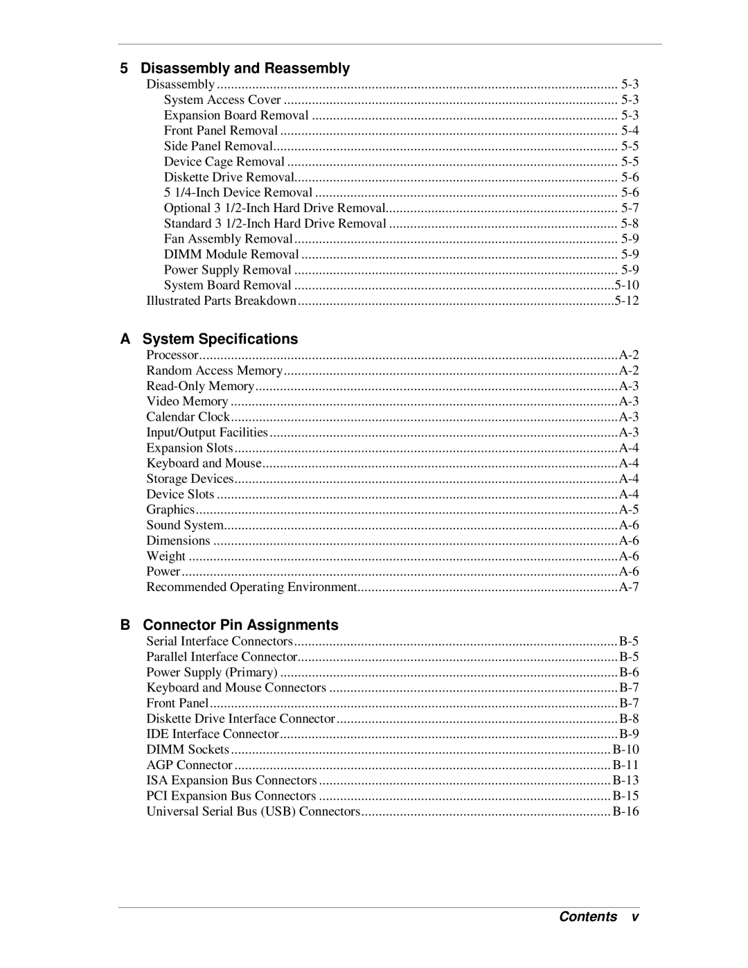
5 Disassembly and Reassembly |
|
Disassembly | |
System Access Cover | |
Expansion Board Removal | |
Front Panel Removal | |
Side Panel Removal | |
Device Cage Removal | |
Diskette Drive Removal | |
5 | |
Optional 3 | |
Standard 3 | |
Fan Assembly Removal | |
DIMM Module Removal | |
Power Supply Removal | |
System Board Removal | |
Illustrated Parts Breakdown |
A System Specifications |
|
Processor | |
Random Access Memory | |
Video Memory | |
Calendar Clock | |
Input/Output Facilities | |
Expansion Slots | |
Keyboard and Mouse | |
Storage Devices | |
Device Slots | |
Graphics | |
Sound System | |
Dimensions | |
Weight | |
Power | |
Recommended Operating Environment |
B Connector Pin Assignments
Serial Interface Connectors | |
Parallel Interface Connector | |
Power Supply (Primary) | |
Keyboard and Mouse Connectors | |
Front Panel | |
Diskette Drive Interface Connector | |
IDE Interface Connector | |
DIMM Sockets | |
AGP Connector | |
ISA Expansion Bus Connectors | |
PCI Expansion Bus Connectors | |
Universal Serial Bus (USB) Connectors |
Contents v
