Concerning the time code and user’s bit
Setting the external time code
1 Set the VTR to the stop mode.
2 Set
3 If the video input has been set to HD SDI input or INT SG, set ![]()
![]()
EXT-L, SLTC or SVITC.
4 If | the video input has been set to SD SDI (when | |
the | optional board has been installed), set | TC |
SRC on the <TC> menu to
Cue time registration, preroll and cue-up
(These functions work only on the HOME, PF1 and PF2 screens.)
• | Registration |
|
|
|
|
|
|
|
| Register the cue time by pressing the | button | ||||||
| while holding down the | button. | F |
|
| |||
• | Presetting |
|
|
|
|
|
|
|
| When the |
| button is | pressed, | the | characters of | ||
|
|
| T |
|
|
|
|
|
| the cue time or TC/UB display | are | highlighted. | |||||
| Turn the ADJ dial to highlight the characters of the | |||||||
| cue time. |
|
|
|
|
|
|
|
| The subsequent steps in the registration procedure | |||||||
| are the same as for TCG. |
|
|
|
| |||
• | Prerolling |
|
|
|
|
|
|
|
| Press the PREROLL button to preroll the tape to | |||||||
| the currently registered CUE point. |
|
|
| ||||
• |
|
|
|
|
|
|
|
|
| Press the PREROLL button while holding down the | |||||||
Fbutton to cue the tape up to the currently registered CUE point.
SET
F1
Time code and user’s bit playback
1 Set the VTR to the stop mode.
2 Set UB.
TC:
The time code is displayed.
UB:
The user’s bit is displayed.
•In the event that it has become impossible to read the time code, it is interpolated using the CTL signal.
3 Press the PLAY button. Playback starts, and the time code appears on the display.
If F1 (SUPER) on the <TC SHIFT> menu is set to
ON, the time code value is superimposed onto the video signals from the VIDEO OUT3 connector.
<Notes>
•While a drop frame time code is being read, the colon between the seconds and frames is replaced with a period.
•If the time code signal is missing, it is interpolated automatically using the CTL signal.
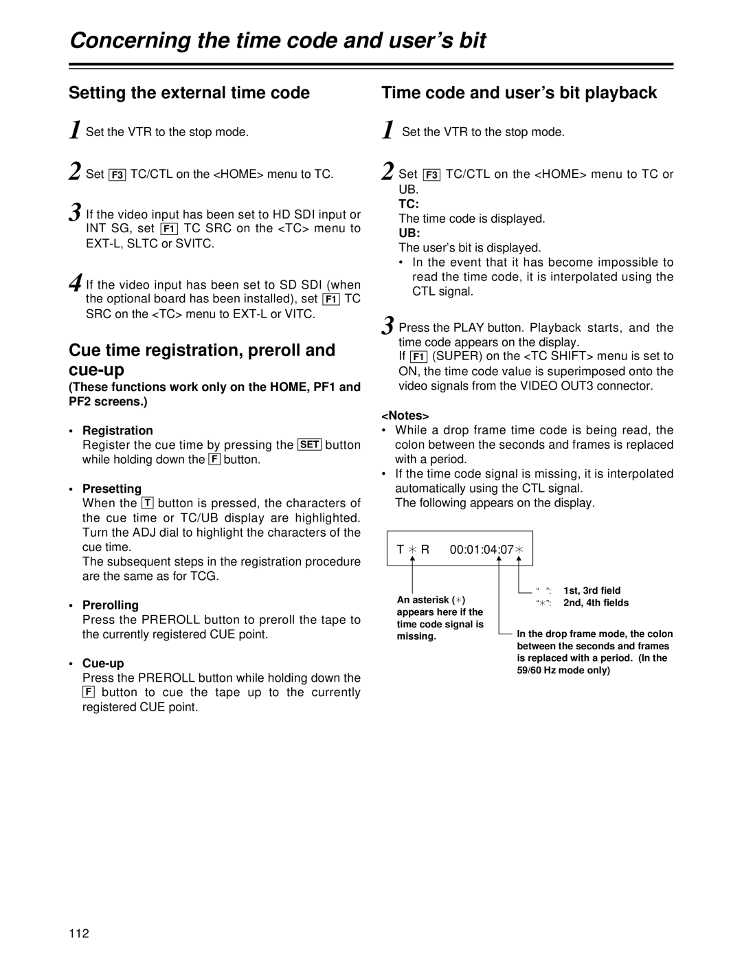
The following appears on the display.
T ¢ R | 00:01:04:07 | ¢ |
| ||||
|
|
|
|
|
|
| “ ”: 1st, 3rd field |
|
|
|
|
|
|
| |
|
|
|
|
|
|
| |
An asterisk ( | ¢ | ) |
|
|
| ||
|
|
| “¢”: 2nd, 4th fields | ||||
appears here if the |
|
|
|
|
| ||
time code signal is |
|
| In the drop frame mode, the colon | ||||
missing. |
|
|
| ||||
|
|
| |||||
between the seconds and frames is replaced with a period. (In the 59/60 Hz mode only)
112