Automatic Editing |
|
|
|
|
|
Checking the edit points
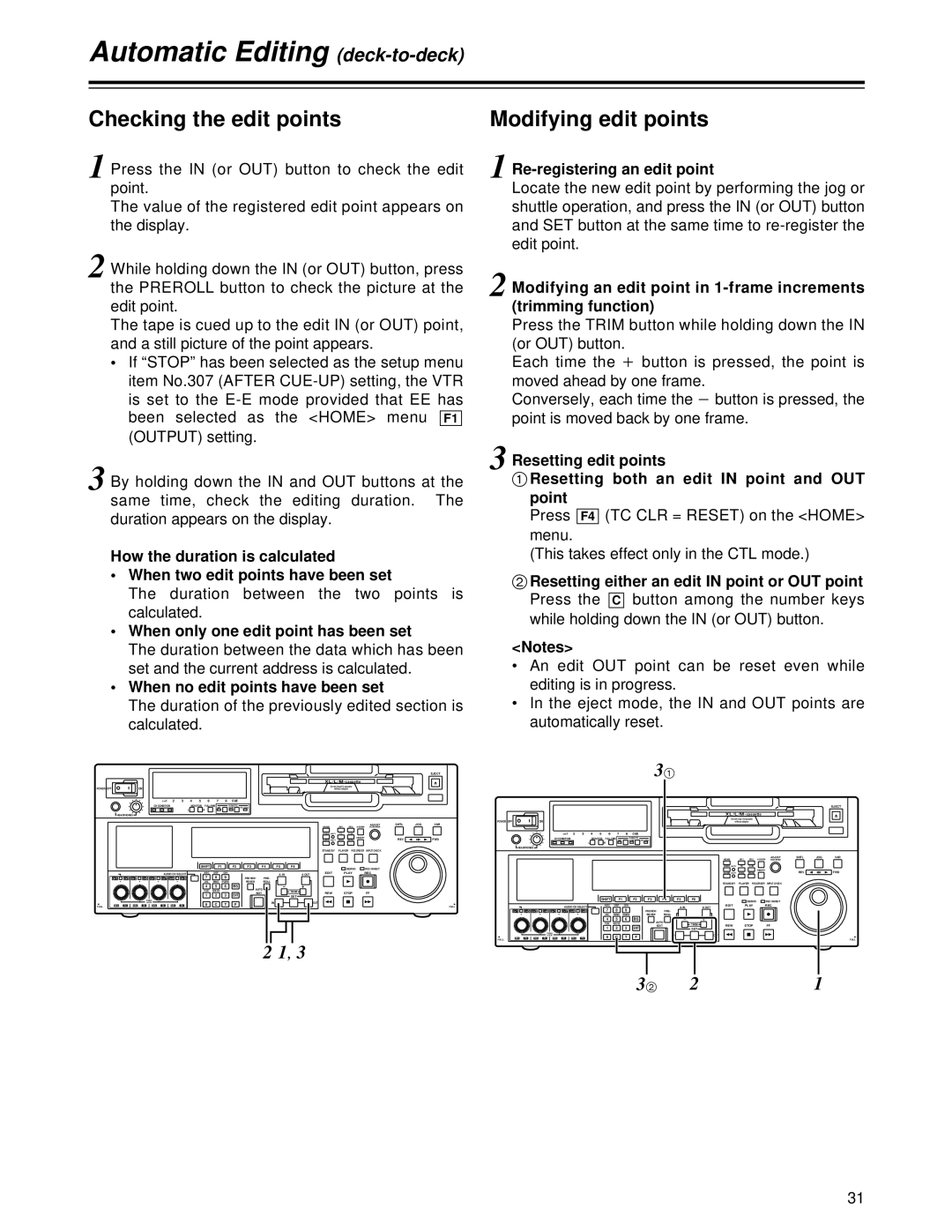
1 Press the IN (or OUT) button to check the edit point.
The value of the registered edit point appears on the display.
2 While holding down the IN (or OUT) button, press the PREROLL button to check the picture at the edit point.
The tape is cued up to the edit IN (or OUT) point, and a still picture of the point appears.
•If “STOP” has been selected as the setup menu item No.307 (AFTER
3 By holding down the IN and OUT buttons at the same time, check the editing duration. The duration appears on the display.
How the duration is calculated
• When two edit points have been set
The duration between the two points is calculated.
•When only one edit point has been set The duration between the data which has been set and the current address is calculated.
•When no edit points have been set
The duration of the previously edited section is calculated.
|
|
|
|
|
|
|
|
|
|
|
|
|
|
|
|
|
|
|
|
| XL/L/M | - cassette |
| ||
POWER | OFF |
|
| ON |
|
|
|
|
|
|
|
|
|
|
|
|
|
|
|
|
| Do not insert |
|
| |
|
|
|
|
|
|
|
|
|
|
|
|
|
|
|
|
|
|
|
| without adapter |
|
| |||
|
|
|
|
|
| CH | 1 | 2 | 3 | 4 | 5 | 6 | 7 | 8 | CUE |
|
|
|
|
|
|
|
|
|
|
|
|
|
|
| CH CONDITION |
|
|
| MONITOR | FULL/FINE |
| REMOTE |
|
|
|
|
|
|
|
|
|
| |||
|
|
|
|
|
|
|
| 9P | 50P |
|
|
|
|
|
|
|
|
|
| ||||||
|
|
|
|
|
|
|
|
|
| L | R |
|
|
|
|
|
|
|
|
|
|
|
|
|
|
| HEADPHONES |
|
|
|
|
|
|
|
|
|
|
|
|
|
|
|
|
|
|
|
|
|
|
| |
|
|
|
|
|
|
|
|
|
|
|
|
|
|
|
|
|
|
|
|
| HOME |
| RF1 | RF2ASSEM | ADJUST |
|
|
|
|
|
|
|
|
|
|
|
|
|
|
|
|
|
|
|
|
|
| ||||
|
|
|
|
|
|
|
|
|
|
|
|
|
|
|
|
|
|
|
|
| VIDEO | UNITY | TC | CUE |
|
|
|
|
|
|
|
|
|
|
|
|
|
|
|
|
|
|
|
|
|
|
|
|
| INSERT | |
|
|
|
|
|
|
|
|
|
|
|
|
|
|
|
|
|
|
|
|
| AUDIO | UNITY | DIAG | MENU |
|
|
|
|
|
|
|
|
|
|
|
|
|
|
|
|
|
|
|
|
|
| STAND BY |
| PLAYER | RECORDER | INPUT CHECK |
|
|
|
|
|
|
|
|
|
|
| SHIFT |
| F1 |
| F2 | F3 | F4 | F5 | F6 |
|
|
|
| SERVO | REC INHIBIT |
|
|
|
|
|
|
|
|
|
|
|
|
|
|
|
|
|
|
|
|
|
|
|
| ||
|
|
|
|
|
|
| AUDIO CH SELECT |
|
| ABC | DEF | GHI |
|
|
|
| A IN |
| A OUT | EDIT |
| PLAY | REC |
| |
| CH 1 | CH | 5 CH 2 | CH | 6 CH 3 | CH | 7 CH | 4 | CH 8 |
| 7 |
| 8 | 9 |
| PREVIEW/ | PRE- |
|
|
|
|
|
|
|
|
|
|
|
|
|
|
|
|
|
|
| JKL | MNO | PQRS |
|
| REVIEW | ROLL |
|
|
|
|
|
|
|
|
|
|
|
|
|
|
|
|
|
|
| 4 |
| 5 | 6 | BS |
| AUTO |
|
|
|
|
|
|
|
|
|
|
|
|
|
|
|
|
|
|
| TUV | WXYZ |
|
|
|
|
| TRIM |
| REW |
| STOP | FF |
| |
|
|
|
|
|
|
|
|
|
|
| 1 |
| 2 | 3 | ENT |
| EDIT |
|
|
|
| ||||
|
|
|
|
|
|
|
|
|
|
|
|
|
|
| SET |
|
|
|
|
|
| ||||
|
|
|
|
| PUSH |
|
|
|
|
|
|
|
|
|
|
|
| IN |
|
| OUT |
|
|
|
|
|
|
|
|
| LOCK |
|
|
|
|
| 0 | C | T | F |
|
|
|
|
|
|
|
|
| ||
FULL | REC | P8 | REC | P8 | REC | P8 |
| REC | P8 |
|
|
|
|
|
|
|
|
|
|
|
| ||||
2 1, 3
F1
|
| EJECT |
SHTL | JOG | VAR |
REV |
| FWD |
FULL
Modifying edit points
1 Re-registering an edit point
Locate the new edit point by performing the jog or shuttle operation, and press the IN (or OUT) button and SET button at the same time to
2 Modifying an edit point in
Press the TRIM button while holding down the IN (or OUT) button.
Each time the
moved ahead by one frame. Conversely, each time the point is moved back by one frame.
3 Resetting edit points
1Resetting both an edit IN point and OUT point
Press F4(TC CLR = RESET) on the <HOME> menu.
(This takes effect only in the CTL mode.)
2Resetting either an edit IN point or OUT point
Press the | buttonC |
| among the number keys |
while holding down the IN (or OUT) button.
<Notes>
•An edit OUT point can be reset even while editing is in progress.
•In the eject mode, the IN and OUT points are automatically reset.
31
|
|
|
|
|
|
|
|
|
|
|
|
|
|
|
|
|
|
|
|
|
| XL/L/M | - cassette |
| ||
POWER | OFF |
|
|
| ON |
|
|
|
|
|
|
|
|
|
|
|
|
|
|
|
|
| Do not insert |
|
| |
|
|
|
|
|
|
|
|
|
|
|
|
|
|
|
|
|
|
|
|
| without adapter |
|
| |||
|
|
|
|
|
|
| CH | 1 | 2 | 3 | 4 | 5 | 6 | 7 | 8 | CUE |
|
|
|
|
|
|
|
|
|
|
|
|
|
|
|
| CH CONDITION |
|
|
| MONITOR | FULL/FINE |
| REMOTE |
|
|
|
|
|
|
|
|
|
| |||
|
|
|
|
|
|
|
|
| 9P | 50P |
|
|
|
|
|
|
|
|
|
| ||||||
|
|
|
|
|
|
|
|
|
|
| L | R |
|
|
|
|
|
|
|
|
|
|
|
|
|
|
|
| HEADPHONES |
|
|
|
|
|
|
|
|
|
|
|
|
|
|
|
|
|
|
|
|
|
|
| |
|
|
|
|
|
|
|
|
|
|
|
|
|
|
|
|
|
|
|
|
|
| HOME |
| RF1 | RF2ASSEM | ADJUST |
|
|
|
|
|
|
|
|
|
|
|
|
|
|
|
|
|
|
|
|
|
|
| ||||
|
|
|
|
|
|
|
|
|
|
|
|
|
|
|
|
|
|
|
|
|
| VIDEO | UNITY | TC | CUE |
|
|
|
|
|
|
|
|
|
|
|
|
|
|
|
|
|
|
|
|
|
|
|
|
|
| INSERT | |
|
|
|
|
|
|
|
|
|
|
|
|
|
|
|
|
|
|
|
|
|
| AUDIO | UNITY | DIAG | MENU |
|
|
|
|
|
|
|
|
|
|
|
|
|
|
|
|
|
|
|
|
|
|
| STAND BY |
| PLAYER | RECORDER | INPUT CHECK |
|
|
|
|
|
|
|
|
|
|
|
| SHIFT |
| F1 |
| F2 | F3 | F4 | F5 | F6 |
|
|
|
| SERVO | REC INHIBIT |
|
|
|
|
|
|
|
|
|
|
|
|
|
|
|
|
|
|
|
|
|
|
|
|
| ||
|
|
|
|
|
|
|
| AUDIO CH SELECT |
|
| ABC | DEF | GHI |
|
|
|
| A IN |
| A OUT | EDIT |
| PLAY | REC |
| |
| CH | 1 | CH | 5 CH 2 | CH | 6 CH 3 | CH | 7 CH | 4 | CH 8 |
| 7 |
| 8 | 9 |
| PREVIEW/ | PRE- |
|
|
|
|
|
|
|
|
|
|
|
|
|
|
|
|
|
|
|
| JKL | MNO | PQRS |
|
| REVIEW | ROLL |
|
|
|
|
|
|
|
|
|
|
|
|
|
|
|
|
|
|
|
| 4 |
| 5 | 6 | BS |
| AUTO |
|
|
|
|
|
|
|
|
|
|
|
|
|
|
|
|
|
|
|
| TUV | WXYZ |
|
|
|
|
| TRIM |
| REW |
| STOP | FF |
| |
|
|
|
|
|
|
|
|
|
|
|
| 1 |
| 2 | 3 | ENT |
| EDIT |
|
|
|
| ||||
|
|
|
|
|
|
|
|
|
|
|
|
|
|
|
| SET |
|
|
|
|
|
| ||||
|
|
|
|
|
| PUSH |
|
|
|
|
|
|
|
|
|
|
|
| IN |
|
| OUT |
|
|
|
|
|
|
|
|
|
| LOCK |
|
|
|
|
| 0 | C | T | F |
|
|
|
|
|
|
|
|
| ||
FULL | REC |
| P8 | REC | P8 | REC | P8 |
| REC | P8 |
|
|
|
|
|
|
|
|
|
|
|
| ||||
|
| EJECT |
SHTL | JOG | VAR |
REV |
| FWD |
FULL
32 | 2 | 1 |
31