4 – Managing Switches | 0 | |||
|
| |||
Displaying Switch Information |
|
| ||
|
|
|
|
|
|
|
|
|
|
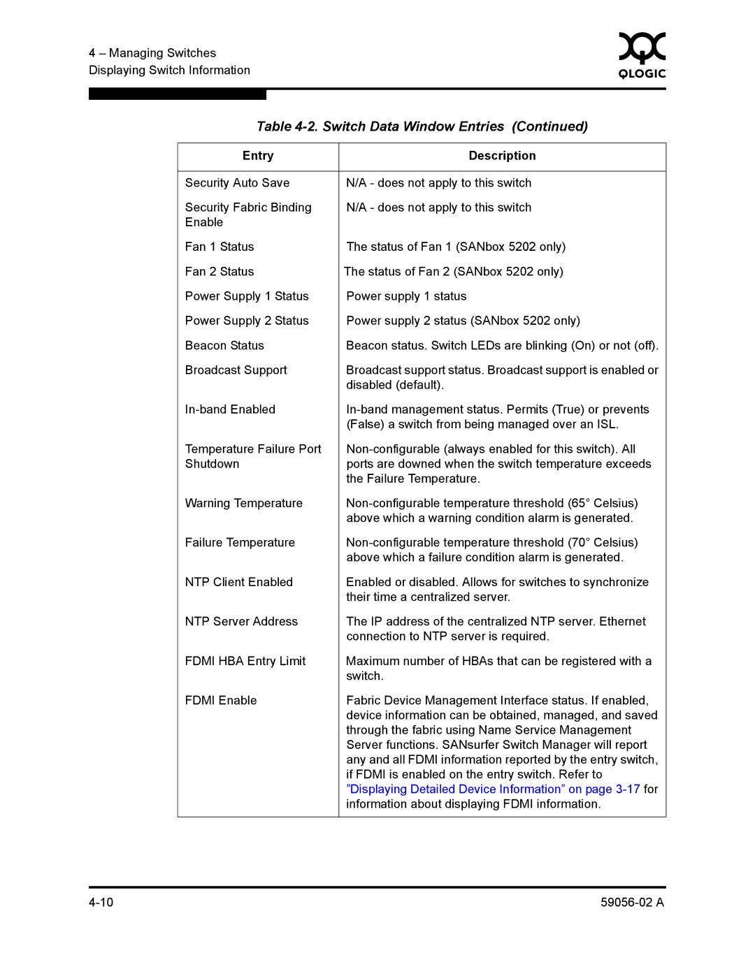
| Table | |||
|
|
|
| |
| Entry | Description |
| |
|
|
|
| |
| Security Auto Save | N/A - does not apply to this switch |
| |
| Security Fabric Binding | N/A - does not apply to this switch |
| |
| Enable |
|
| |
| Fan 1 Status | The status of Fan 1 (SANbox 5202 only) |
| |
| Fan 2 Status | The status of Fan 2 (SANbox 5202 only) |
| |
| Power Supply 1 Status | Power supply 1 status |
| |
| Power Supply 2 Status | Power supply 2 status (SANbox 5202 only) |
| |
| Beacon Status | Beacon status. Switch LEDs are blinking (On) or not (off). |
| |
| Broadcast Support | Broadcast support status. Broadcast support is enabled or |
| |
|
|
| disabled (default). |
|
|
| |||
|
|
| (False) a switch from being managed over an ISL. |
|
| Temperature Failure Port |
| ||
| Shutdown | ports are downed when the switch temperature exceeds |
| |
|
|
| the Failure Temperature. |
|
| Warning Temperature |
| ||
|
|
| above which a warning condition alarm is generated. |
|
| Failure Temperature |
| ||
|
|
| above which a failure condition alarm is generated. |
|
| NTP Client Enabled | Enabled or disabled. Allows for switches to synchronize |
| |
|
|
| their time a centralized server. |
|
| NTP Server Address | The IP address of the centralized NTP server. Ethernet |
| |
|
|
| connection to NTP server is required. |
|
| FDMI HBA Entry Limit | Maximum number of HBAs that can be registered with a |
| |
|
|
| switch. |
|
| FDMI Enable | Fabric Device Management Interface status. If enabled, |
| |
|
|
| device information can be obtained, managed, and saved |
|
|
|
| through the fabric using Name Service Management |
|
|
|
| Server functions. SANsurfer Switch Manager will report |
|
|
|
| any and all FDMI information reported by the entry switch, |
|
|
|
| if FDMI is enabled on the entry switch. Refer to |
|
|
|
| ”Displaying Detailed Device Information” on page |
|
|
|
| information about displaying FDMI information. |
|
|
|
|
|
|