2 – General Description | 0 | |
|
| |
Chassis Controls and LEDs |
|
|
|
|
|
|
|
|
2.1
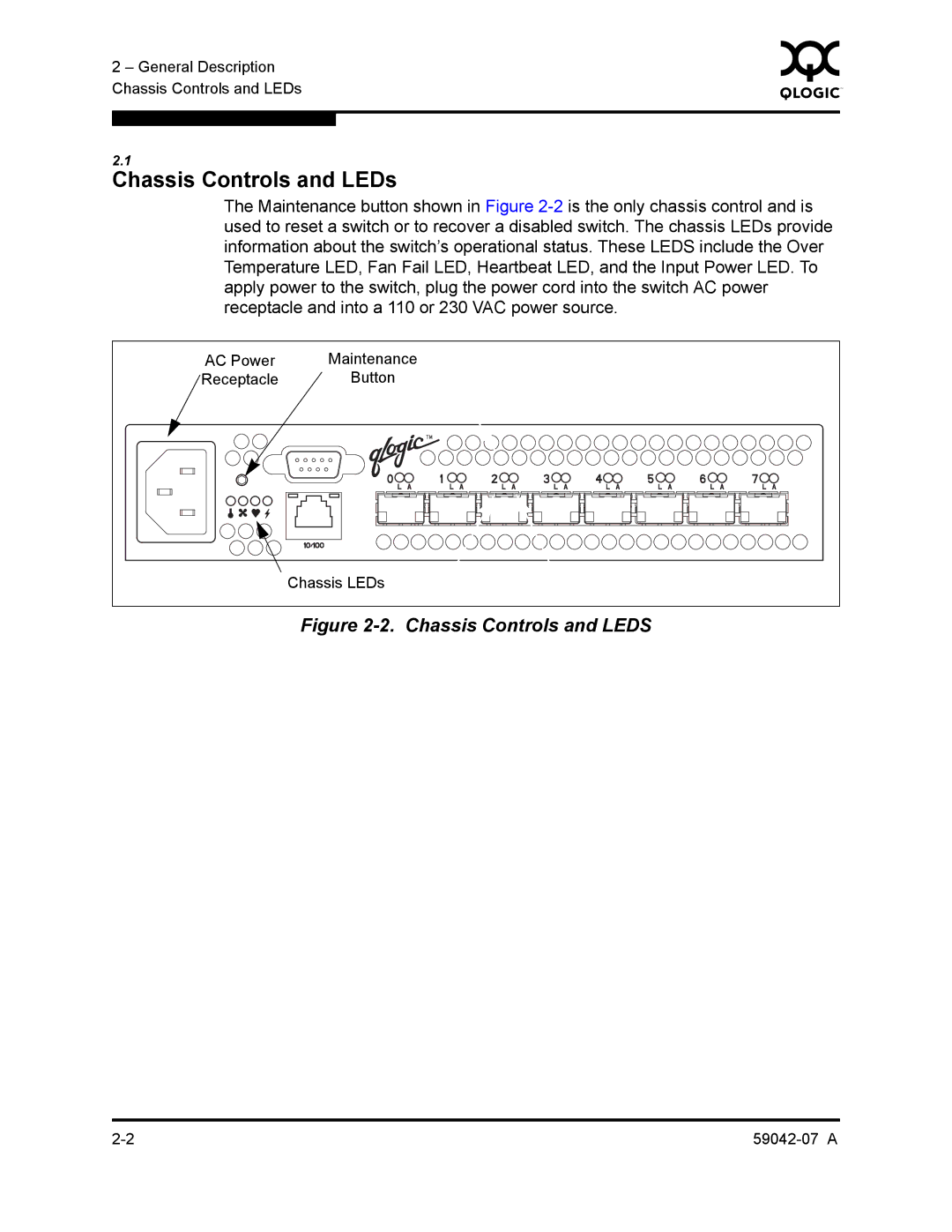
Chassis Controls and LEDs
The Maintenance button shown in Figure
AC Power | Maintenance |
Receptacle | Button |
| Chassis LEDs |
2 – General Description | 0 | |
|
| |
Chassis Controls and LEDs |
|
|
|
|
|
|
|
|
2.1
The Maintenance button shown in Figure
AC Power | Maintenance |
Receptacle | Button |
| Chassis LEDs |