Manuals
/
Samson
/
Household Appliance
/
Thermostat
Samson
5100 operating instructions Option, EB 5179 EN, Type 5244, Type
Models:
5179
5100
1
93
142
142
Download
142 pages
31.78 Kb
90
91
92
93
94
95
96
97
<
>
Gradient characteristic
Install
2.4Configuring universal inputs
Connecting the sensors
2.6Resetting to default values
Error alarms
5.6Delayed outdoor temperature adaptation
1.5Setting the controller time
5.5Deactivation depending on outdoor temperature
Modem timeout t
Page 93
Image 93
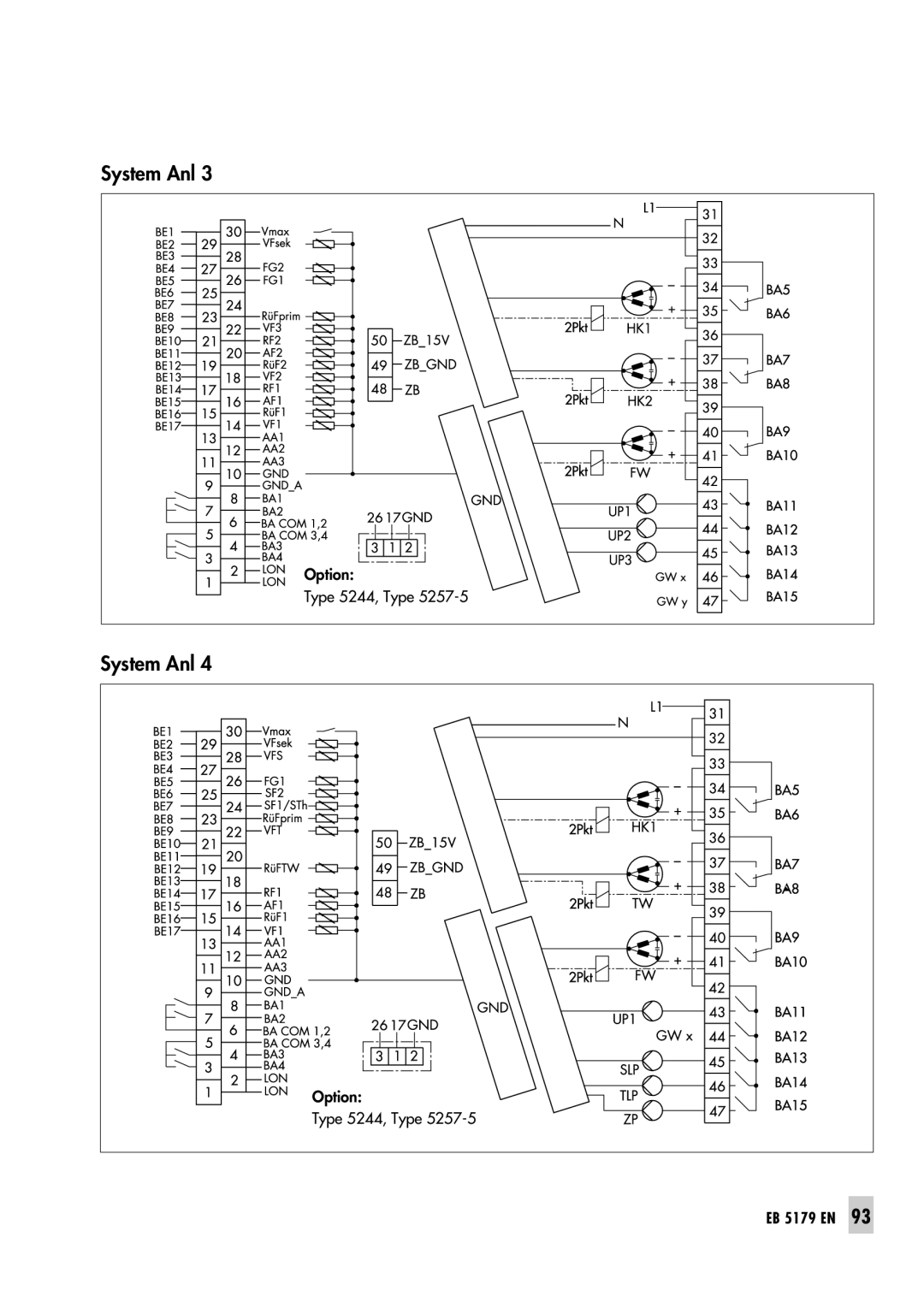
System Anl 3
Option:
Type 5244, Type
5257-5
System Anl 4
Option:
Type 5244, Type
5257-5
EB 5179 EN
93
Page 92
Page 94
Page 93
Image 93
Page 92
Page 94
Contents
Automation System TROVIS
Mounting and Operating Instructions EB 5179 EN
District Heating Controller TROVIS
Firmware version Edition August
Disclaimer of liability
Contents
Contents
5.10
Contents
Error alarms
1.1Operating elements
1 Operation
1.1.1 Operating keys
Operation
Operation
1.1.2 Operating switches
Operation
1.2Operating modes
Operation
1.3Display
Operation
1.4Displaying data
Operation
1.5Setting the controller time
Operation
Change year setting Confirm year
Confirm date Display: Year
Activate editing mode for the controller year
Operation
1.6Setting the times-of-use
Activate editing mode for times-of-use
Operation
Operation
1.6.1 Copying the times-of-use
Operation
1.6.2 Entering public holidays
Deleting a public holiday
Operation
Confirm selection Select
Delete the public holiday
Operation
1.6.3 Entering vacation periods
Return to the operating level
Operation
Deleting vacation periods
Confirm selection Select – – – –
Start-up
2 Start-up 2.1Setting the system code number
Start-up
2.2Activating and deactivating functions
Start-up
Confirm settings
Start-up
2.3Changing parameters
2.3.1 Enter key number
2.4Configuring universal inputs
2.5Calibrating sensors
Start-up
Proceed as follows
Start-up
Start-up
2.6Resetting to default values
Manual operation
3 Manual operation
Systems
Systems
BE BA AE RK
Systems
EB 5179 EN
k RKHK
Systems
Default setting Co1 ->Fb00 Co1 ->Fb01 Co1 ->Fb02
Systems
Default setting
System Anl
Systems
Systems
Default setting
Systems
Default setting Co1 ->Fb00 Co1 ->Fb01 Co1 ->Fb02
Co2 ->Fb00 Co2 ->Fb01 Co2 ->Fb02 Co3 ->Fb00
Co3 ->Fb01 Co3 ->Fb02 Co5 ->Fb00
RKTW
Systems
36EB 5179 EN
Systems
Systems
Default setting Co1 ->Fb00 Co1 ->Fb01 Co1 ->Fb02
Systems
Default setting Co1 ->Fb00 Co1 ->Fb01 Co1 ->Fb02
5.1Functioning principle
5 Functions of the heating circuit
5.2Weather-compensatedcontrol
Functions of the heating circuit
5.2.1 Gradient characteristic
5.2.2 4-pointcharacteristic
Functions of the heating circuit
Functions
Functions of the heating circuit
Functions of the heating circuit
5.3Fixed set point control
5.5Deactivation depending on outdoor temperature
5.5.1 OT deactivation value in rated operation
5.5.2 OT deactivation value in reduced operation
5.5.3 OT activation value in rated operation
5.5.4 Summer mode
Functions of the heating circuit
5.6Delayed outdoor temperature adaptation
5.7Outdoor temperature-dependentadvance heating
Functions of the heating circuit
5.9Optimization with room sensor
5.8Remote operation
Configuration
Functions of the heating circuit
Functions of the DHW circuit
5.10 Flash adaptation
5.11 Adaptation
Functions of the DHW circuit
Appendix
5.12 Room temperature-dependentcontrol
Appendix
5.13 Pump management
BA1, BA3: Circulation pump on and off
BA2, BA4: Reduce pump speed
5.14 Releasing the heating circuit
5.15 Position feedback in pre-controlcircuit
Appendix
Functions of the DHW circuit
6 Functions of the DHW circuit
System-widefunctions
6.2DHW heating in the storage tank system
Appendix
Start storage tank charging
Stop storage tank charging
Appendix
6.3Priority operation
6.3.1 Reverse control
Appendix
6.4Forced charging of the DHW storage tank
6.3.2 Set-backoperation
6.5Thermal disinfection of the DHW storage tank
Appendix
Functions
Appendix
7 System-widefunctions
7.4Return flow temperature limitation
7.1Automatic summer time/winter time changeover
7.2Frost protection
System-widefunctions
–the heating systems have been calibrated
7.6Compensating for time delays
7.5Condensate accumulation control
System-widefunctions
System-widefunctions
7.7Three-stepcontrol
7.8On/off control
7.9Continuous-actioncontrol
System-widefunctions
System-widefunctions
7.10 Forwarding the outdoor temperature
System-widefunctions
Settings for capacity limitation
Example to determine the limit value
30 kW
7.12 Locking manual level
Settings for flow rate limitation
System-widefunctions
8.1Error list/sensor failure
Operational faults
Operational faults
8.2Collective error alarm
Number = Bit no. in HR
Operational faults
Operational faults
8.3Temperature monitoring
Upper limit: Any
Operational faults
Operational faults
8.5Error status register
Operational faults
8.6Error alarms
Example of a transfer to the control system
<w> = D0 x <1> + D1 x <2> +...+ D11 x <2048>
Operational faults
8.6.2 Sending fax in case of a fault alarm
Functions
Operational faults
Communication
9 Communication
9.1RS-232-Csystem bus interface
Communication
GND TD DTR DCD RD RTS
Functions
Communication
Station address ST.-NR
Communication
Communication
Modem timeout t
9.4Meter bus interface
9.4.1 Activating the meter bus
Communication
Flow temperature b, C
Return flow temperature b, C
Communication
energy
Communication
Capacity limitation
Flow rate capacity
Communication
9.5LON communication
Communication
9.6Requesting/processing an external demand
Sending outdoor temperatures
Communication
Sending the controller time
EB 5179 EN
Communication
Installation
10 Installation
Installation
Controller housing
Panel mounting
Back of the
11 Electrical connection
Connecting the sensors
Option
Option
Option
Type 5244, Type
Option
Option
EB 5179 EN
Type 5244, Type
Option
Option
94EB 5179 EN
Type 5244, Type
Option
Option
Type 5244, Type
EB 5179 EN
Option
Electrical connection
Voltage supply 24 V/30 mA
Article no. 29 66
12 Appendix 12.1 Function block lists
Appendix
Co1 to Co3 Heating circuit 1 to
Comments
Appendix
Co4: DHW heating
Appendix
Comments
Appendix
Co5: General functions and pre-controlcircuit
Comments
Appendix
Fb Function
Comments
Appendix
Co6: Sensor initialization
Co7: LON communication
Co8: Error initialization
Comments
Appendix
12.2 Parameter list
Appendix
PA1 to PA3: Heating circuits HK1 to HK3
Display
Appendix
Display
Appendix
Display
Appendix
Display
Appendix
PA4: DHW heating
Appendix
Display
Appendix
PA5: Capacity and flow rate limitation
Appendix
Display
Appendix
Display
Appendix
Maximum flow rate of the entire system
Appendix
Maximum flow rate of the heating
Maximum flow rate of the DHW heating
Display
Appendix
PA9: Communication
Appendix
Display
Appendix
Appendix
12.3 Display
Display
Appendix
Inf4: DHW heating
Appendix
Display
Appendix
Return flow temperature at sensor RüF or RüFprim
Charging temperature
Appendix
Inf5: District heating circuit
Inf8: Error status register/sensor failure
Appendix
InF7: LON communication
InF9 Communication
Appendix
Appendix
12.4 Sensor resistance tables
Appendix
12.5 Technical data
Function block settings in configuration levels
12.6 Customer data
Appendix
Station Operator Relevant SAMSON office
Parameters
Parameters
Appendix
Page
Parameters
Appendix
PA5 System-wideparameters
Parameters
Appendix
1732
Key number
Co9: Modbus and meter bus communication
Index
Interface
Index
Time-controlledoperation
Index
InF1
2006-03
EB 5179 EN