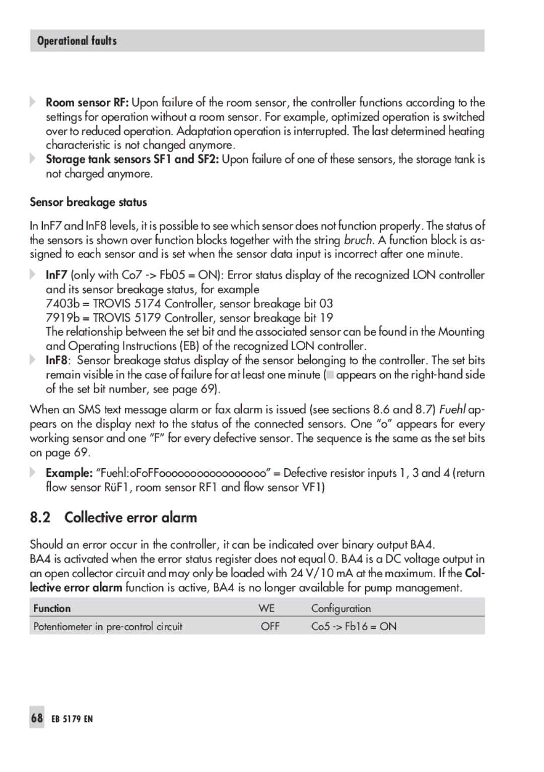
5179, 5100 specifications
The Samson 5179 and 5100 series are renowned for their innovative design and robust performance in various industrial applications. These models are particularly known for their precision control and reliability in managing fluid flow systems.One of the main features of the Samson 5179 is its advanced control valve technology, which allows for seamless operation across different pressures and flow rates. The valve is designed with a compact and lightweight construction, making it easy to install and maintain. Enhanced sealing mechanisms ensure minimal leakage and increased durability, even under harsh operating conditions.
The Samson 5100, on the other hand, is distinguished by its adaptive control technologies. This model incorporates state-of-the-art automation capabilities, allowing for remote monitoring and adjustments. With its integrated sensors, operators can receive real-time data on pressure, temperature, and flow rates, leading to more informed decision-making.
Both series utilize high-quality materials, ensuring longevity and resistance to corrosion and wear. This characteristic is crucial for applications in industries such as water treatment, chemicals, and pharmaceuticals. The valves are designed to withstand significant pressure differences, enhancing their versatility in various settings.
Another key technology featured in both the 5179 and 5100 series is the user-friendly interface. This interface simplifies configuration and management, enabling operators to program performance parameters quickly. The intuitive design minimizes the learning curve, allowing teams to leverage the system’s capabilities effectively.
Additionally, both models are compliant with international standards, making them suitable for global applications. This compliance not only ensures safety but also enhances market acceptance across various regions.
Energy efficiency is another important characteristic of the Samson 5179 and 5100 series. With optimized flow dynamics, these valves minimize energy consumption while maintaining high performance, making them a sustainable choice for companies aiming to reduce their environmental footprint.
In summary, the Samson 5179 and 5100 series stand out due to their innovative features, robust construction, and advanced technologies. With a focus on precision, reliability, and efficiency, these models are poised to meet the evolving demands of modern industrial applications. Their adaptability and user-friendly interfaces make them ideal for operators seeking streamlined operations and enhanced productivity.

