113.197611
113.197511
Part No. SP5539
Contents
Safety Symbol and Signal Words
Safety
Major Hazards
KWARNING
Wrong Way Feed Hazard
Personal Safety Instructions
Safety Instructions
Work Area Safety Instructions
Saw Safety Instructions
Workpiece Safety Instructions
Blade Safety Instructions
On-Product Safety Labels
KWARNING
Safety
Assembly
Identify Parts
QJlIF*llfq!lt
LHllLltlLllltllllltB
Tools Needed For Assembly
Assembly Steps
Build Cabinet Base
Build Foot Assemblies
Shaped Slot
Attach Foot Assemblies
Short
Assemble Side PanelsOnly Door Model without Casters
Assembly
Attach Door Hinges
Attach/Install Spacers
Attach Side Panels to Bottom Shelf
Attach Skirts
Center Support Upper Lower
Attach Doors
Complete Center Slide Assembly
Only Drawer Model
Center Support
Assemble Drawers
Attach Handwheel
Mount Motor
Shaft has left-hand threa&. Turn nut clock- wise to loosen
Assembly
Mount Basic Saw Assembly
Adjust Leveling Feet
Attach Trim Caps
Install Front Table
Attach Slide Arm Supports
Clips. Note Table will extend about Beyond Trim caps
Assemble Table Lock Mechanism
Install Drawers Only Drawer Model
Alignment and Adjustment
To Remove Drawers Only Drawer Model
Controls
45, -45 , 90
Rip l.ock
Controls
Alignment and Adjustment Steps
Alignment and Adjustment
Adjust Column Support
Level Front Table
Square Crosscut Travel
Install Blade
Square Blade to Table for Crosscut- ting
Alignment and Adjustment
Square Blade to Fence
Square Blade to Table for Ripping
Adjust Carriage Bearings
Make Blade Parallel to Table
Install Guard
Align Spreader to Blade
Complete Adjustments
Go to Digital Display Section and follow
Error Messages
Digital Display
Button Functions
=73
Install Battery
To Replace Battery
Align Encoders
Miter Encoder
Set Zero Reference Points For Bevel, Miter, and Elevation
Bevel Encoder
Set Zero Reference Point For Rip
Set Zero Reference Point For Out-Rip
Conversion Table
Motor Specifications
Power Supply
Motor Protection & Reset Button
Electrical Connections
To avoid electric shock, unplug saw
To Change Motor Voltage to 240 A.C
Before changing Motor voltage
Crosscutting Safety
Crosscutting
During crosscutting, blade teeth can
Having fingers, hand or arm cut off
Crosscuttin
Crosscut Kerfs
Making Crosscuts
Step
Repetitive Crosscutting
Ripping
Ripping Defined
In-Rip and Out-Rip Positions
Infeed and Outfeed Directions
Ripping Safety
Workpiece Positioning
Kickback
Pinching or binding can happen when
Ripping
Wrong Way Feed
Guard Nose Function
Pawls and Spreader Function
If workpiece is pushed along fence
Ripping Set-up Procedure
With kerfs, workpiece could get
Making Rip Cuts
Inleed
Ripping Hints
Dado Blades, Molding Heads
Cutting Aides
Fences
Push Sticks
Auxiliary Fence and Push Block for Ripping
Cutting Aides
Cutting Aides
Straight Edge for Irregular Workpiece
Information for Dado
Accessories Safety
Information for Edging
Lower Blade Guard
Edging without an auxiliary fence
Lower blade guard can get caught or
Accessories
Jam in fence or table kerfs
Maintenance
Cleaning
General Information
Lubrication
Adjustments for Wear
Remove screw and nut from swivel lock knob
Carriage Bearings
Arm and Column
Blade Changing
Replacing Pawls
Possible Causes
Motor Problem
What to Do
Troubleshooting
Troubleshooting
Cutting Problem
Saw Problem
Possible Causes
Troubleshooting
Electronics Problem
Blank
Repair Parts
Model NOS .197411 and 113.197511
Repair Parts
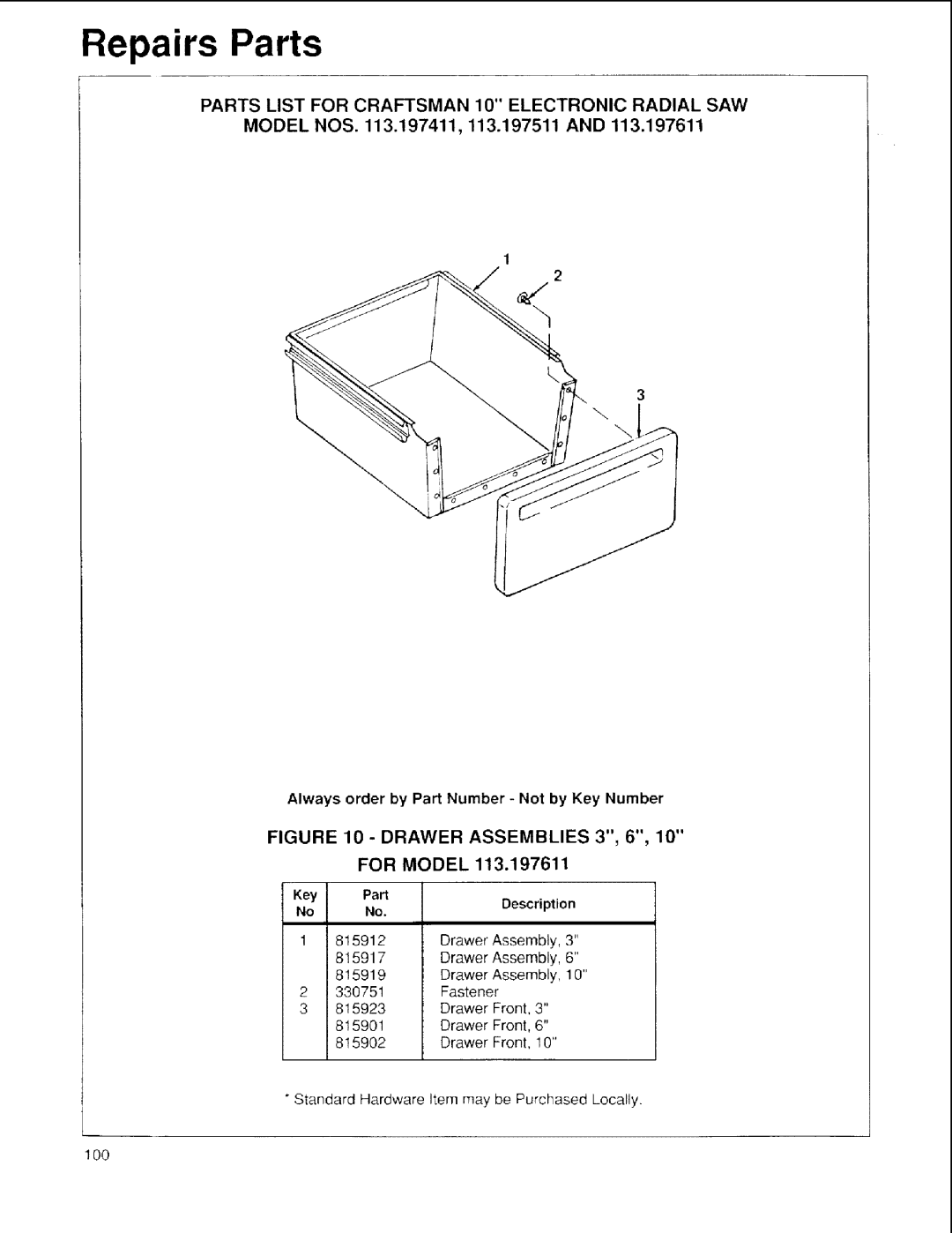
Always order by Part Number Not by Key Number
Model NOS .197411 and 113.197611
Base and Column Assembly
Model NOS .197411 and 113.197511
Parts List for Craftsman 10 Electronic Radial SAW
Model NOS .197411 and 113.197611
Model NOS .197411 and 113.197511
Model NOS .197411 and 113.197611 and 113,197511
Part
Repair Parts
ARM Assembly
Table Assembly
Foot Assembly Model 113.197511
Model NOS .197411, 113.197511
Repairs Parts
Model NOS .197411, 113.197511
Repairs Parts
Cabinet Assembly for Model 113.197411
For
Model
Motor Assembly
Guard Assembly
Index
113.197411
Sold by SEARS, Roebuck and CO., Chicago, IL 60684 U.S.A
Pail No. SP5539