Assembly
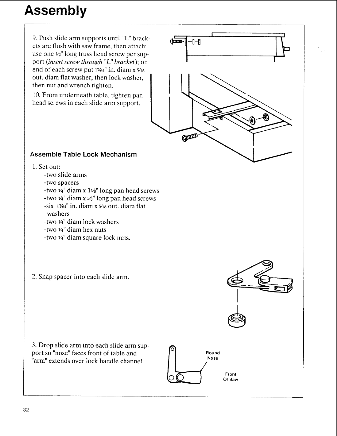
9.Push slide arm supports until "L" brack- ets are flush with saw frame, then attach: use one V2"long truss head screw per sup- port (insert screw through "L" bracket); on end of each screw put 17/d' in. diam x 9h6
out. diam flat washer, then lock washer, | L | |
| ||
then nut and wrench tighten. |
| |
10. From underneath | table, tighten pan |
|
head screws in each slide arm support.
Assemble Table Lock Mechanism
1. Set out:
washers
2. Snap spacer into each slide arm.
÷
3.Drop slide arm into each slide arm sup- port so "nose" faces front of table and "arm" extends over lock handle channel.
Fronl
Of Saw
32