Alignment and Adjustment
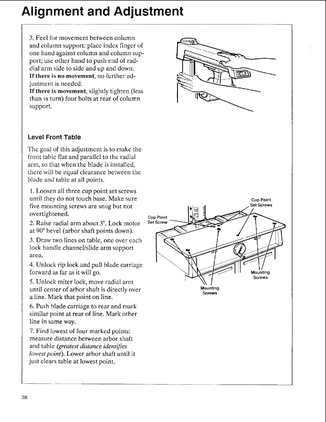
3. Feel for movement between column
and column support: place index finger of one hand against column and column sup- port; use other hand to push end of rad- dial arm side to side and up and down.
If there is no movement, no further ad- justment is needed.
If there is movement, slightly tighten (less
than _ turn) four bolts at rear of column
support.
Level Front Table
The goal of this adjustment is to make the front table flat and parallel to the radial arm, so that when the blade is installed, there will be equal clearance between the blade and table at all points.
1.Loosen all three cup point set screws until they do not touch base. Make sure five mounting screws are snug but not overtightened.
2.Raise radial arm about 3". Lock motor at 90 ° bevel (arbor shaft points down).
3.Draw two lines on table, one over each
lock handle channel/slide arm support area.
4.Unlock rip lock and pull blade carriage forward as far as it will go.
5.Unlock miter lock, move radial arm until center of arbor shaft is directly over a line. Mark that point on line.
6.Push blade carriage to rear and mark similar point at rear of line. Mark other line in same way.
7.Find lowest of four marked points: measure distance between arbor shaft
and table (greatest distance identifies" lowest point). Lower arbor shaft until it just clears table at lowest point.
Cup Point Set Screw
Cup Point
Set Screws
Mounting
Screws
Mounting
Screws
38