Alignment and Adjustment
Adjust Carriage Bearings
The goal of this adjustment is to eliminate looseness between the carriage bearings and the radial arm. The blade carriage should roll freely along the entire length of the radial arm, but with some resistance.
1.With blade still locked in
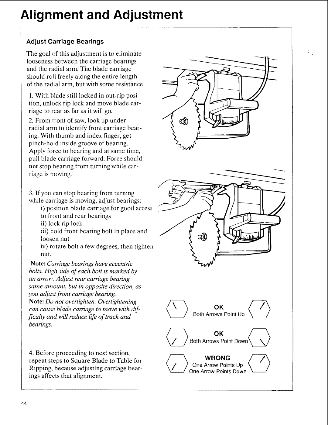
2.From front of saw, look up under
radial arm to identify front carriage bear- ing. With thumb and index finger, get
3.If you can stop bearing from turning
while carriage is moving, adjust bearings:
i)position blade carriage for good access to front and rear bearings
ii)lock rip lock
iii)hold front bearing bolt in place and loosen nut
iv)rotate bolt a few degrees, then tighten
nut.
Note: Carriage bearings have eccentric bolts. High side of each bolt is marked by an arrow. Adjust rear carriage bearing same amount, but in opposite direction, as you adjust front carriage bearing.
Note: Do not overtighten, gh, ertightening can cause blade carriage to move with dif- ficulty and will reduce life of track and bearings.
4.Before proceeding to next section, repeat steps to Square Blade to Table for Ripping, because adjusting carriage bear- ings affects that alignment.
OK
Both Arrows Point Up
OKpoint Down@
One Arrow Points Up One Arrow Points Down
44