Bevel Encoder
1.Turn display on.
2.Lock radial arm at 0 ° miter. Lock motor at 0 ° bevel.
3.Push BEVEL button.
4.Push REF SET button. Display will read:
5.Support motor, unlock bevel lock,
move motor counterclockwise until it
snaps into
6.Support motor, unlock bevel lock,
move motor counterclockwise until it
snaps into next
(blade horizontal) and lock bevel lock. Display should read:
7. If display reads as it should, bevel en-
coder is aligned
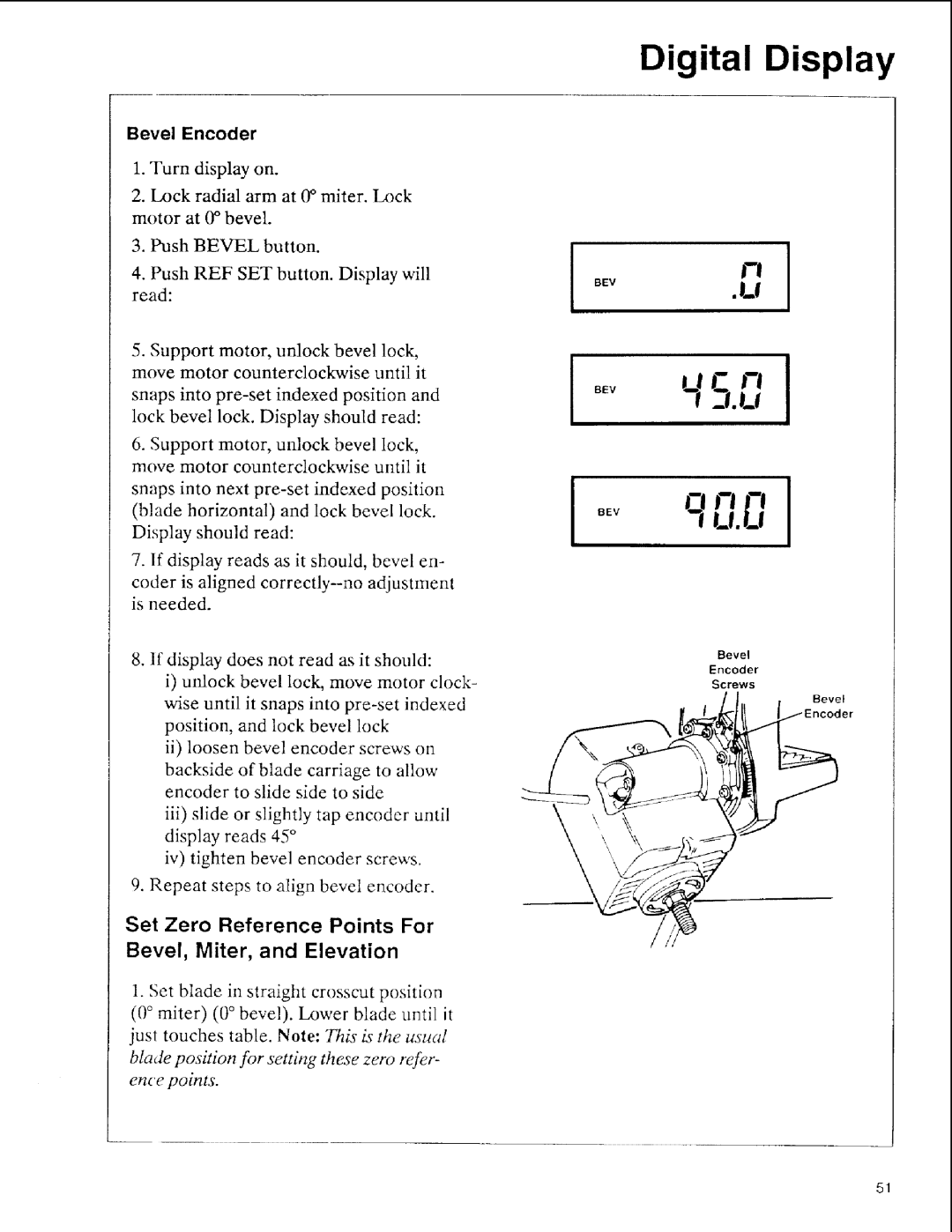
8.If display does not read as it should:
i)unlock bevel lock, move motor clock- wise until it snaps into
ii)loosen bevel encoder screws on
backside of blade carriage to allow encoder to slide side to side
iii)slide or slightly tap encoder until display reads 45 °
iv)tighten bevel encoder screws.
9.Repeat steps to align bevel encoder.
Set Zero Reference Points For
Bevel, Miter, and Elevation
1. Set blade in straight crosscut position
(0 ° miter) (0 ° bevel). Lower blade until it just touches table. Note: This i_ the usual blade position for settb N these zero refer- ence points.
Digital Display
V!
BEv •U
£1.U [
BEVq'U.U -"I-'
Bevel
Encoder
Screws
Bevel
51