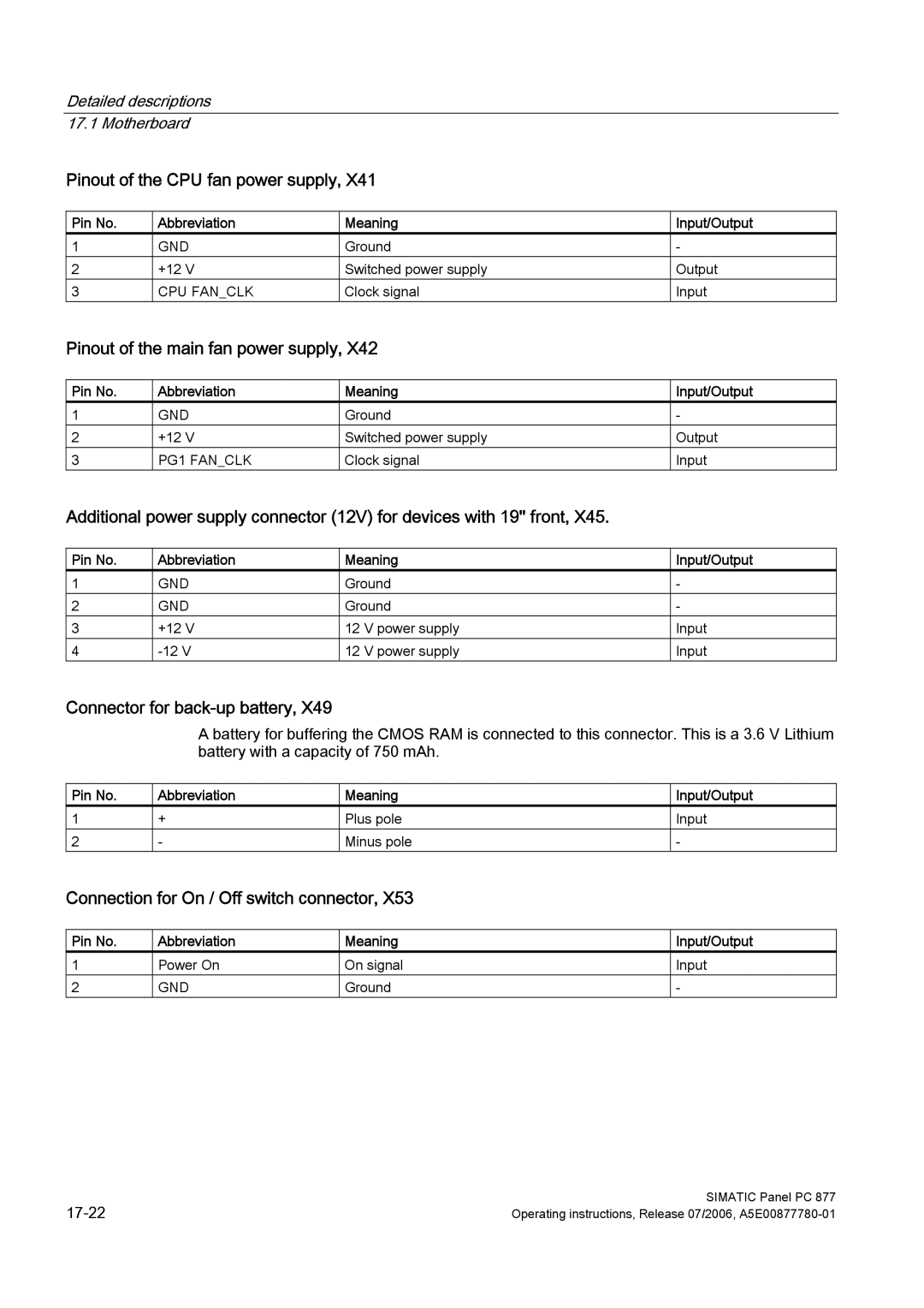
Detailed descriptions 17.1 Motherboard
Pinout of the CPU fan power supply, X41
Pin No. | Abbreviation | Meaning | Input/Output |
1 | GND | Ground | - |
2 | +12 V | Switched power supply | Output |
3 | CPU FAN_CLK | Clock signal | Input |
Pinout of the main fan power supply, X42
Pin No. | Abbreviation | Meaning | Input/Output |
1 | GND | Ground | - |
2 | +12 V | Switched power supply | Output |
3 | PG1 FAN_CLK | Clock signal | Input |
Additional power supply connector (12V) for devices with 19'' front, X45.
Pin No. | Abbreviation | Meaning | Input/Output |
1 | GND | Ground | - |
2 | GND | Ground | - |
3 | +12 V | 12 V power supply | Input |
4 | 12 V power supply | Input |
Connector for back-up battery, X49
A battery for buffering the CMOS RAM is connected to this connector. This is a 3.6 V Lithium battery with a capacity of 750 mAh.
Pin No. | Abbreviation | Meaning | Input/Output |
1 | + | Plus pole | Input |
2 | - | Minus pole | - |
Connection for On / Off switch connector, X53
Pin No. | Abbreviation | Meaning | Input/Output |
1 | Power On | On signal | Input |
2 | GND | Ground | - |
SIMATIC Panel PC 877 | |
Operating instructions, Release 07/2006, |
