|
|
|
|
|
|
|
| www.ti.com |
|
|
|
|
| ||||
|
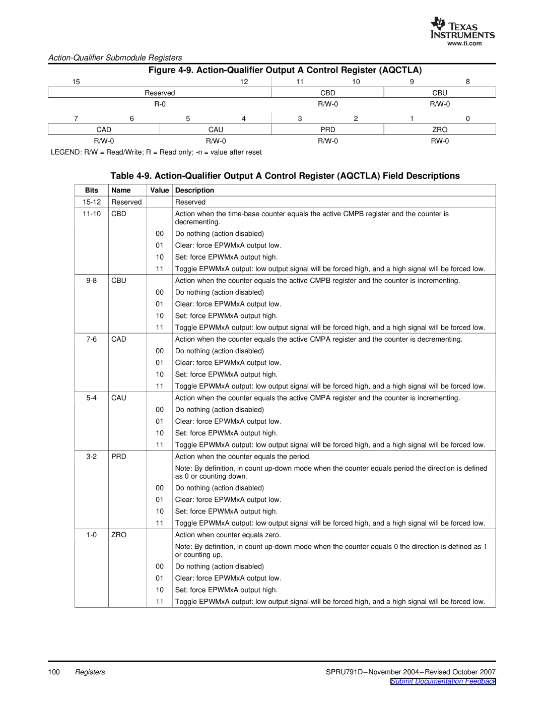
| Figure |
| |||||
15 |
|
|
| 12 | 11 | 10 | 9 | 8 |
|
| Reserved |
|
|
| CBD |
| CBU |
|
|
|
|
|
| |||
7 | 6 |
| 5 | 4 | 3 | 2 | 1 | 0 |
CAD |
| CAU |
|
| PRD |
| ZRO | |
|
|
|
| |||||
LEGEND: R/W = Read/Write; R = Read only; |
|
|
|
| ||||
| Table | |||||||
Bits | Name | Value | Description |
|
|
|
|
|
Reserved |
| Reserved |
|
|
|
|
| |
CBD |
| Action when the | ||||||
|
|
| decrementing. |
|
|
|
|
|
|
| 00 | Do nothing (action disabled) |
|
|
|
| |
|
| 01 | Clear: force EPWMxA output low. |
|
|
|
| |
|
| 10 | Set: force EPWMxA output high. |
|
|
|
| |
|
| 11 | Toggle EPWMxA output: low output signal will be forced high, and a high signal will be forced low. | |||||
CBU |
| Action when the counter equals the active CMPB register and the counter is incrementing. | ||||||
|
| 00 | Do nothing (action disabled) |
|
|
|
| |
|
| 01 | Clear: force EPWMxA output low. |
|
|
|
| |
|
| 10 | Set: force EPWMxA output high. |
|
|
|
| |
|
| 11 | Toggle EPWMxA output: low output signal will be forced high, and a high signal will be forced low. | |||||
CAD |
| Action when the counter equals the active CMPA register and the counter is decrementing. | ||||||
|
| 00 | Do nothing (action disabled) |
|
|
|
| |
|
| 01 | Clear: force EPWMxA output low. |
|
|
|
| |
|
| 10 | Set: force EPWMxA output high. |
|
|
|
| |
|
| 11 | Toggle EPWMxA output: low output signal will be forced high, and a high signal will be forced low. | |||||
CAU |
| Action when the counter equals the active CMPA register and the counter is incrementing. | ||||||
|
| 00 | Do nothing (action disabled) |
|
|
|
| |
|
| 01 | Clear: force EPWMxA output low. |
|
|
|
| |
|
| 10 | Set: force EPWMxA output high. |
|
|
|
| |
|
| 11 | Toggle EPWMxA output: low output signal will be forced high, and a high signal will be forced low. | |||||
PRD |
| Action when the counter equals the period. |
|
|
| |||
|
|
| Note: By definition, in count | |||||
|
|
| as 0 or counting down. |
|
|
|
| |
|
| 00 | Do nothing (action disabled) |
|
|
|
| |
|
| 01 | Clear: force EPWMxA output low. |
|
|
|
| |
|
| 10 | Set: force EPWMxA output high. |
|
|
|
| |
|
| 11 | Toggle EPWMxA output: low output signal will be forced high, and a high signal will be forced low. | |||||
ZRO |
| Action when counter equals zero. |
|
|
|
| ||
|
|
| Note: By definition, in count | |||||
|
|
| or counting up. |
|
|
|
|
|
|
| 00 | Do nothing (action disabled) |
|
|
|
| |
|
| 01 | Clear: force EPWMxA output low. |
|
|
|
| |
|
| 10 | Set: force EPWMxA output high. |
|
|
|
| |
|
| 11 | Toggle EPWMxA output: low output signal will be forced high, and a high signal will be forced low. | |||||
100 | Registers | |
|
| Submit Documentation Feedback |
