www.ti.com
Controlling Multiple Buck Converters With Independent Frequencies
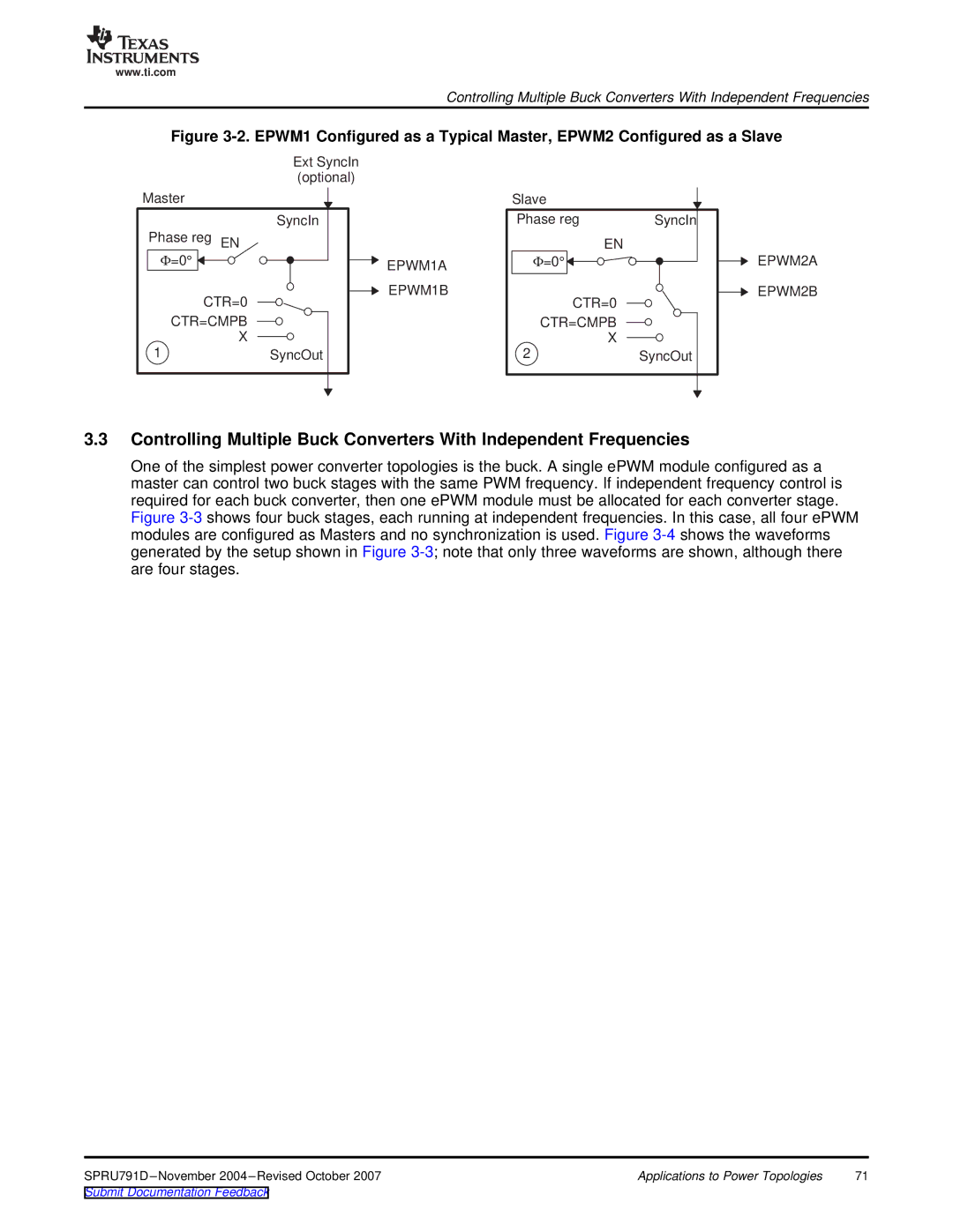
Figure 3-2. EPWM1 Configured as a Typical Master, EPWM2 Configured as a Slave
| Ext SyncIn |
| (optional) |
Master |
|
| SyncIn |
Phase reg EN |
|
Φ=0° | EPWM1A |
| |
CTR=0 | EPWM1B |
| |
CTR=CMPB |
|
X |
|
1 | SyncOut |
Slave
Phase reg | SyncIn |
| EN |
Φ=0° |
|
CTR=0
CTR=CMPB X
2SyncOut
EPWM2A
EPWM2B
3.3Controlling Multiple Buck Converters With Independent Frequencies
One of the simplest power converter topologies is the buck. A single ePWM module configured as a master can control two buck stages with the same PWM frequency. If independent frequency control is required for each buck converter, then one ePWM module must be allocated for each converter stage. Figure
Applications to Power Topologies | 71 |