www.ti.com
4.1Time-Base Submodule Registers
Figure 4-1 through Figure 4-5 and Table 4-1 through Table 4-5 provide the time-base register definitions.
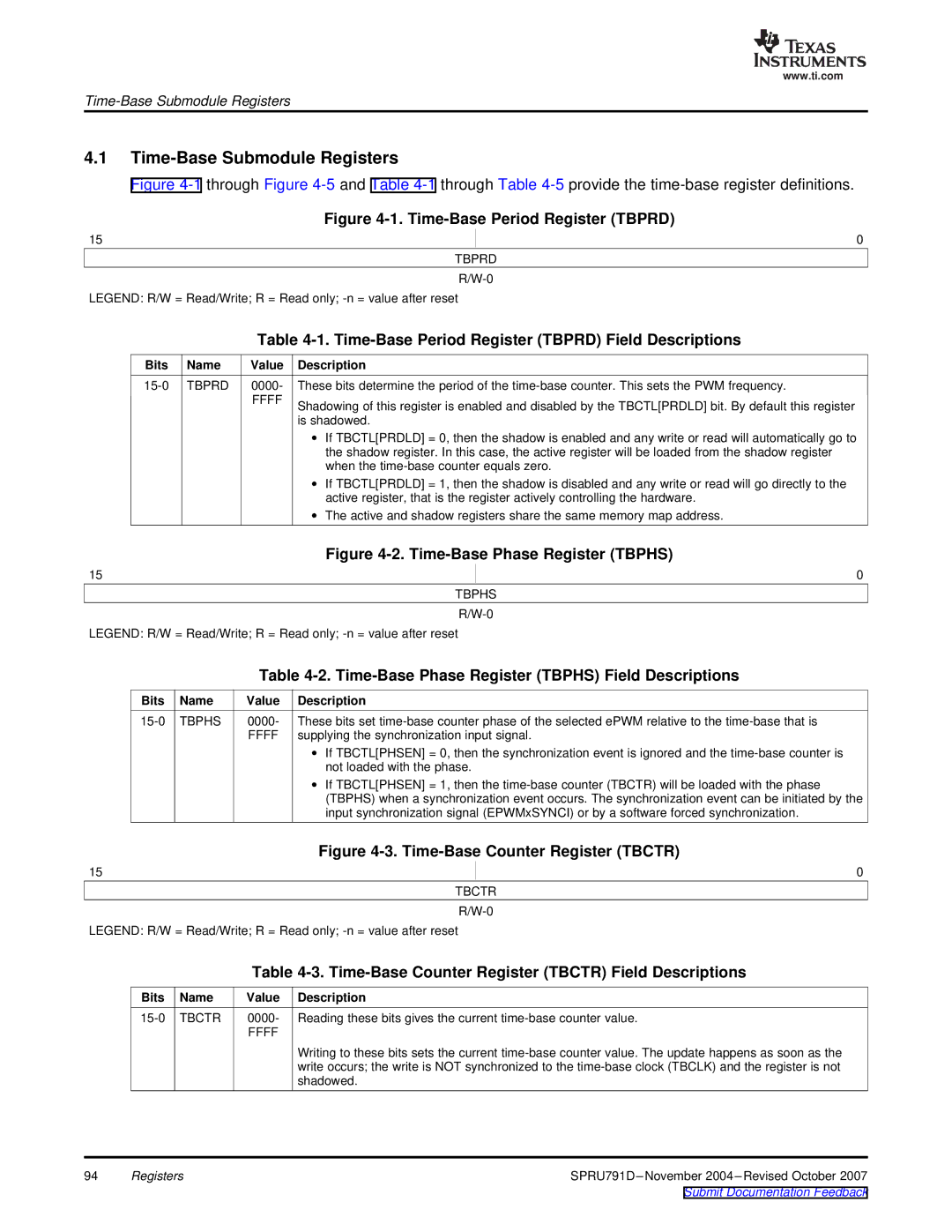
Figure 4-1. Time-Base Period Register (TBPRD)
15 | 0 |
TBPRD
LEGEND: R/W = Read/Write; R = Read only;
| Table |
Bits Name | Value Description |
FFFF
These bits determine the period of the
Shadowing of this register is enabled and disabled by the TBCTL[PRDLD] bit. By default this register is shadowed.
∙If TBCTL[PRDLD] = 0, then the shadow is enabled and any write or read will automatically go to the shadow register. In this case, the active register will be loaded from the shadow register when the
∙If TBCTL[PRDLD] = 1, then the shadow is disabled and any write or read will go directly to the active register, that is the register actively controlling the hardware.
∙The active and shadow registers share the same memory map address.
| Figure |
15 | 0 |
TBPHS
LEGEND: R/W = Read/Write; R = Read only;
|
| Table |
Bits | Name | Value Description |
TBPHS | 0000- These bits set |
FFFFsupplying the synchronization input signal.
∙If TBCTL[PHSEN] = 0, then the synchronization event is ignored and the
∙If TBCTL[PHSEN] = 1, then the
Figure 4-3. Time-Base Counter Register (TBCTR)
15 | 0 |
TBCTR
LEGEND: R/W = Read/Write; R = Read only;
|
| Table |
Bits | Name | Value Description |
TBCTR | 0000- Reading these bits gives the current | |
|
| FFFF |
Writing to these bits sets the current
94 | Registers |