www.ti.com
Overview of Multiple Modules
3.1Overview of Multiple Modules
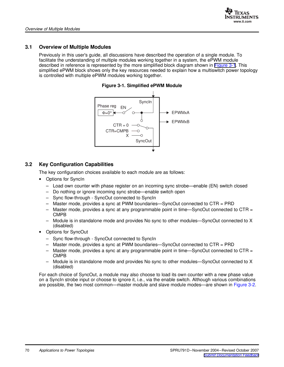
Previously in this user's guide, all discussions have described the operation of a single module. To facilitate the understanding of multiple modules working together in a system, the ePWM module described in reference is represented by the more simplified block diagram shown in Figure
Figure 3-1. Simplified ePWM Module
Phase reg | SyncIn | |
EN | ||
| ||
Φ=0° |
| |
CTR = 0 | ||
CTR=CMPB | ||
| X | |
| SyncOut | |
EPWMxA
EPWMxB
3.2Key Configuration Capabilities
The key configuration choices available to each module are as follows:
∙Options for SyncIn
–Load own counter with phase register on an incoming sync
–Do nothing or ignore incoming sync
–Sync
–Master mode, provides a sync at PWM
–Master mode, provides a sync at any programmable point in
CMPB
–Module is in standalone mode and provides No sync to other
∙Options for SyncOut
–Sync
–Master mode, provides a sync at PWM
–Master mode, provides a sync at any programmable point in
CMPB
–Module is in standalone mode and provides No sync to other
For each choice of SyncOut, a module may also choose to load its own counter with a new phase value on a SyncIn strobe input or choose to ignore it, i.e., via the enable switch. Although various combinations are possible, the two most
70 | Applications to Power Topologies |