www.ti.com
2.5Dead-Band Generator (DB) Submodule
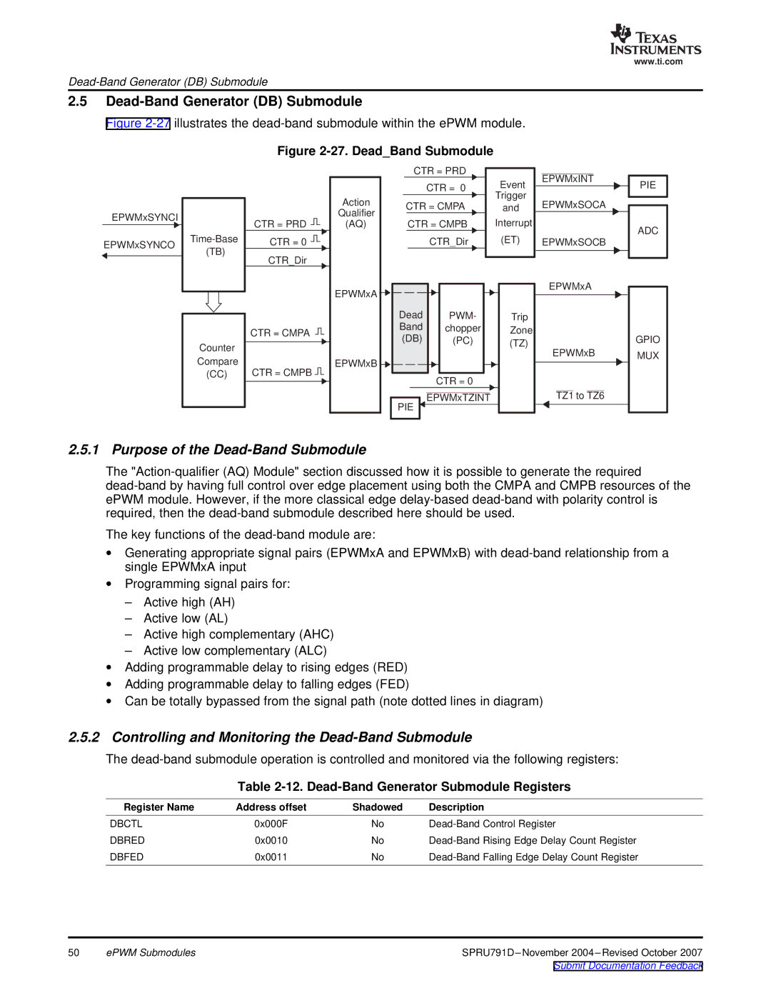
Figure 2-27 illustrates the dead-band submodule within the ePWM module.
Figure 2-27. Dead_Band Submodule
EPWMxSYNCI
EPWMxSYNCO
(TB)
CTR = PRD ![]()
![]()
CTR = 0 ![]()
![]()
CTR_Dir
Action
Qualifier
(AQ)
| CTR = PRD |
|
|
|
|
|
|
| Event |
| EPWMxINT |
|
|
| CTR = 0 |
| ||||
|
|
|
|
| ||
| Trigger |
|
|
|
| |
CTR = CMPA |
| EPWMxSOCA |
| |||
and |
|
| ||||
|
| |||||
| CTR = CMPB | Interrupt |
|
|
|
|
| CTR_Dir | (ET) |
| EPWMxSOCB |
| |
|
|
|
|
|
|
|
|
|
|
|
|
|
|
PIE
ADC
Counter
Compare
(CC)
CTR = CMPA
CTR = CMPB ![]()
![]()
EPWMxA
EPWMxB
Dead | PWM- | Trip |
Band | chopper | Zone |
(DB) | (PC) | (TZ) |
| CTR = 0 |
|
PIE | EPWMxTZINT |
|
|
|
EPWMxA
EPWMxB
TZ1 to TZ6
GPIO MUX
2.5.1 Purpose of the Dead-Band Submodule
The
The key functions of the
∙Generating appropriate signal pairs (EPWMxA and EPWMxB) with
∙Programming signal pairs for:
–Active high (AH)
–Active low (AL)
–Active high complementary (AHC)
–Active low complementary (ALC)
∙Adding programmable delay to rising edges (RED)
∙Adding programmable delay to falling edges (FED)
∙Can be totally bypassed from the signal path (note dotted lines in diagram)
2.5.2Controlling and Monitoring the Dead-Band Submodule
The
Table 2-12. Dead-Band Generator Submodule Registers
Register Name | Address offset | Shadowed | Description |
DBCTL | 0x000F | No | |
DBRED | 0x0010 | No | |
DBFED | 0x0011 | No |
50 | ePWM Submodules | |
|
| Submit Documentation Feedback |