www.ti.com
Overview
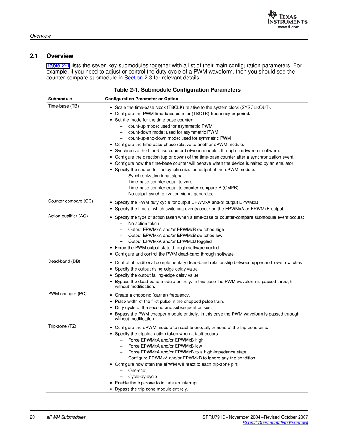
2.1Overview
Table
|
| Table | |
Submodule | Configuration Parameter or Option | ||
∙ | Scale the | ||
| ∙ | Configure the PWM | |
| ∙ | Set the mode for the | |
|
| – | |
|
| – | |
|
| – | |
| ∙ | Configure the | |
| ∙ | Synchronize the | |
| ∙ | Configure the direction (up or down) of the | |
| ∙ | Configure how the | |
| ∙ | Specify the source for the synchronization output of the ePWM module: | |
|
| – | Synchronization input signal |
|
| – | |
|
| – | |
|
| – No output synchronization signal generated. | |
∙ | Specify the PWM duty cycle for output EPWMxA and/or output EPWMxB | ||
| ∙ | Specify the time at which switching events occur on the EPWMxA or EPWMxB output | |
∙ | Specify the type of action taken when a | ||
|
| – | No action taken |
|
| – Output EPWMxA and/or EPWMxB switched high | |
|
| – Output EPWMxA and/or EPWMxB switched low | |
|
| – Output EPWMxA and/or EPWMxB toggled | |
| ∙ | Force the PWM output state through software control | |
| ∙ | Configure and control the PWM | |
| ∙ | Control of traditional complementary | |
| ∙ | Specify the output | |
| ∙ | Specify the output | |
| ∙ | Bypass the | |
|
| without modification. | |
∙ | Create a chopping (carrier) frequency. | ||
| ∙ | Pulse width of the first pulse in the chopped pulse train. | |
| ∙ | Duty cycle of the second and subsequent pulses. | |
| ∙ | Bypass the | |
|
| without modification. | |
∙ | Configure the ePWM module to react to one, all, or none of the | ||
| ∙ | Specify the tripping action taken when a fault occurs: | |
|
| – Force EPWMxA and/or EPWMxB high | |
|
| – Force EPWMxA and/or EPWMxB low | |
|
| – Force EPWMxA and/or EPWMxB to a | |
|
| – Configure EPWMxA and/or EPWMxB to ignore any trip condition. | |
| ∙ | Configure how often the ePWM will react to each | |
|
| – | |
|
| – | |
| ∙ | Enable the | |
| ∙ | Bypass the | |
20 | ePWM Submodules | |
|
| Submit Documentation Feedback |