www.ti.com
Table
Bits | Name | Value | Description |
|
| 1 | Enable Interrupt generation; a |
1 | CBC |
| |
|
| 0 | Disable |
|
| 1 | Enable interrupt generation; a |
|
|
| interrupt. (1) |
0 | Reserved |
| Reserved |
(1)The Peripheral Interrupt Expansion (PIE) module is described in the specific device version of the System Control and Interrupts Reference Guide listed in Section 1.
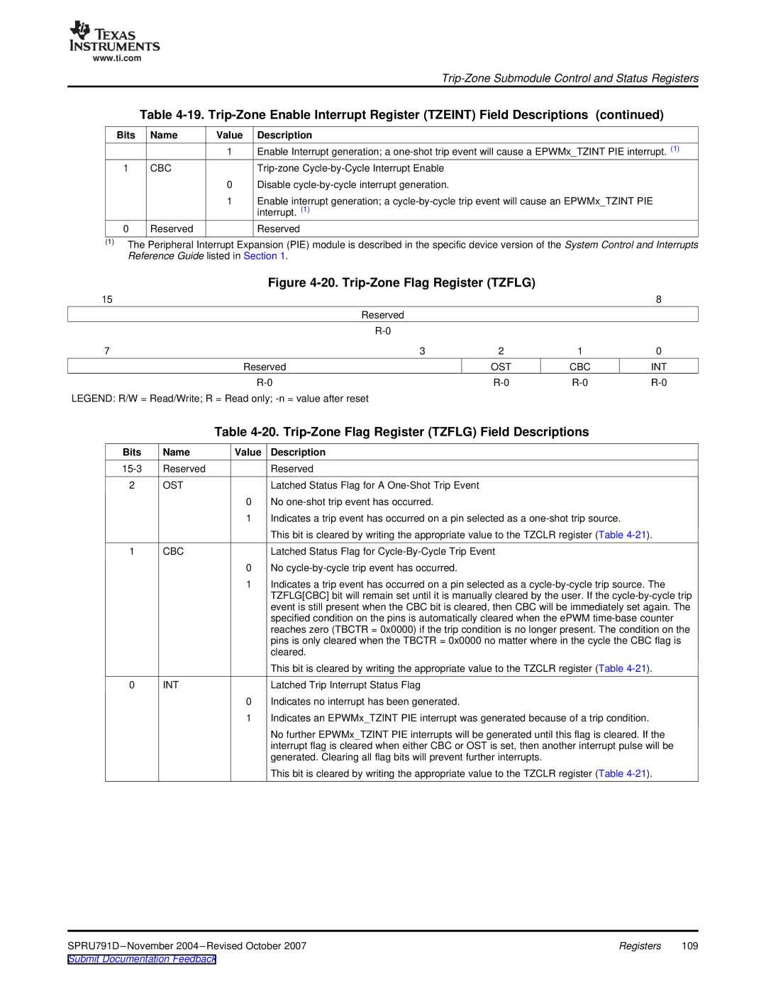
Figure 4-20. Trip-Zone Flag Register (TZFLG)
15 |
|
|
| 8 |
| Reserved |
|
|
|
|
|
|
| |
7 | 3 | 2 | 1 | 0 |
Reserved |
| OST | CBC | INT |
|
LEGEND: R/W = Read/Write; R = Read only;
Table 4-20. Trip-Zone Flag Register (TZFLG) Field Descriptions
Bits | Name | Value | Description |
Reserved |
| Reserved | |
2 | OST |
| Latched Status Flag for A |
|
| 0 | No |
|
| 1 | Indicates a trip event has occurred on a pin selected as a |
|
|
| This bit is cleared by writing the appropriate value to the TZCLR register (Table |
1 | CBC |
| Latched Status Flag for |
|
| 0 | No |
|
| 1 | Indicates a trip event has occurred on a pin selected as a |
|
|
| TZFLG[CBC] bit will remain set until it is manually cleared by the user. If the |
|
|
| event is still present when the CBC bit is cleared, then CBC will be immediately set again. The |
|
|
| specified condition on the pins is automatically cleared when the ePWM |
|
|
| reaches zero (TBCTR = 0x0000) if the trip condition is no longer present. The condition on the |
|
|
| pins is only cleared when the TBCTR = 0x0000 no matter where in the cycle the CBC flag is |
|
|
| cleared. |
|
|
| This bit is cleared by writing the appropriate value to the TZCLR register (Table |
0 | INT |
| Latched Trip Interrupt Status Flag |
|
| 0 | Indicates no interrupt has been generated. |
|
| 1 | Indicates an EPWMx_TZINT PIE interrupt was generated because of a trip condition. |
|
|
| No further EPWMx_TZINT PIE interrupts will be generated until this flag is cleared. If the |
|
|
| interrupt flag is cleared when either CBC or OST is set, then another interrupt pulse will be |
|
|
| generated. Clearing all flag bits will prevent further interrupts. |
This bit is cleared by writing the appropriate value to the TZCLR register (Table
Registers | 109 |