www.ti.com
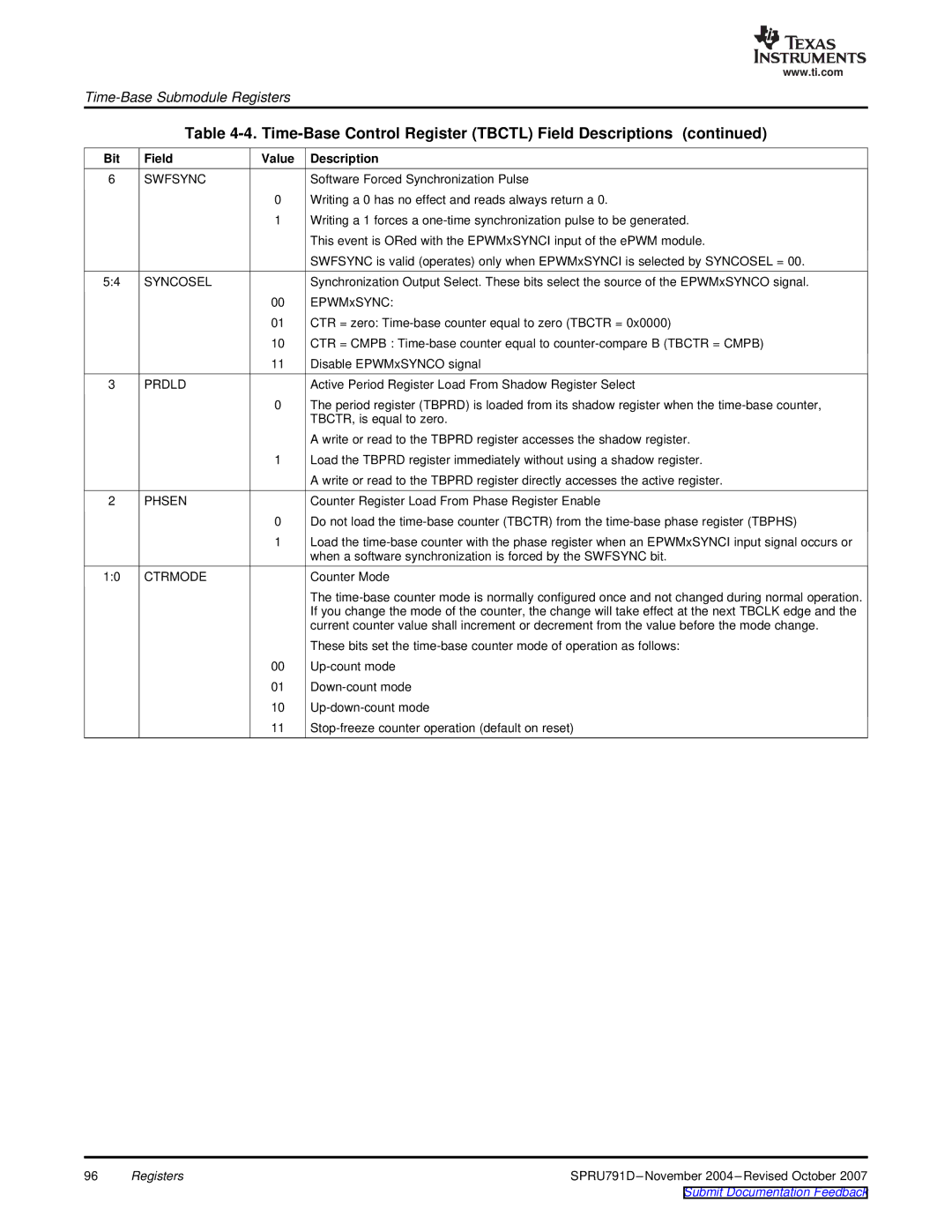
Table 4-4. Time-Base Control Register (TBCTL) Field Descriptions (continued)
Bit | Field | Value | Description |
6 | SWFSYNC |
| Software Forced Synchronization Pulse |
|
| 0 | Writing a 0 has no effect and reads always return a 0. |
|
| 1 | Writing a 1 forces a |
|
|
| This event is ORed with the EPWMxSYNCI input of the ePWM module. |
|
|
| SWFSYNC is valid (operates) only when EPWMxSYNCI is selected by SYNCOSEL = 00. |
5:4 | SYNCOSEL |
| Synchronization Output Select. These bits select the source of the EPWMxSYNCO signal. |
|
| 00 | EPWMxSYNC: |
|
| 01 | CTR = zero: |
|
| 10 | CTR = CMPB : |
|
| 11 | Disable EPWMxSYNCO signal |
3 | PRDLD |
| Active Period Register Load From Shadow Register Select |
|
| 0 | The period register (TBPRD) is loaded from its shadow register when the |
|
|
| TBCTR, is equal to zero. |
|
|
| A write or read to the TBPRD register accesses the shadow register. |
|
| 1 | Load the TBPRD register immediately without using a shadow register. |
|
|
| A write or read to the TBPRD register directly accesses the active register. |
2 | PHSEN |
| Counter Register Load From Phase Register Enable |
|
| 0 | Do not load the |
|
| 1 | Load the |
|
|
| when a software synchronization is forced by the SWFSYNC bit. |
1:0 | CTRMODE |
| Counter Mode |
|
|
| The |
|
|
| If you change the mode of the counter, the change will take effect at the next TBCLK edge and the |
|
|
| current counter value shall increment or decrement from the value before the mode change. |
|
|
| These bits set the |
|
| 00 | |
|
| 01 | |
|
| 10 | |
|
| 11 |
96 | Registers |