www.ti.com
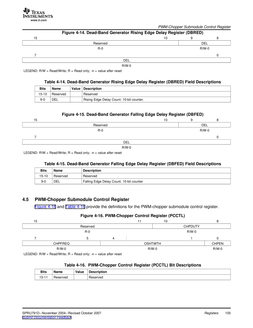
Figure 4-14. Dead-Band Generator Rising Edge Delay Register (DBRED)
15 | 10 | 9 | 8 |
Reserved |
|
| DEL |
|
| ||
7 |
|
| 0 |
DEL
LEGEND: R/W = Read/Write; R = Read only;
Table
Bits | Name | Value Description |
|
|
Reserved | Reserved |
|
| |
DEL | Rising Edge Delay Count. |
|
| |
| Figure |
| ||
15 |
| 10 | 9 | 8 |
|
| Reserved | DEL |
|
|
|
| ||
7 |
|
|
| 0 |
|
| DEL |
|
|
|
|
|
| |
LEGEND: R/W = Read/Write; R = Read only;
Table
Bits | Name | Description |
Reserved | Reserved | |
DEL | Falling Edge Delay Count. |
4.5PWM-Chopper Submodule Control Register
Figure 4-16 and Table 4-16 provide the definitions for the PWM-chopper submodule control register.
Figure 4-16. PWM-Chopper Control Register (PCCTL)
15 |
|
| 11 | 10 | 8 |
| Reserved |
|
| CHPDUTY |
|
|
|
|
| ||
7 | 5 | 4 |
| 1 | 0 |
| CHPFREQ |
|
| OSHTWTH | CHPEN |
|
|
|
LEGEND: R/W = Read/Write; R = Read only;
Table 4-16. PWM-Chopper Control Register (PCCTL) Bit Descriptions
Bits | Name | Value Description |
Reserved | Reserved |
Registers | 105 | |
Submit Documentation Feedback |
|
|
