www.ti.com
2.6PWM-Chopper (PC) Submodule
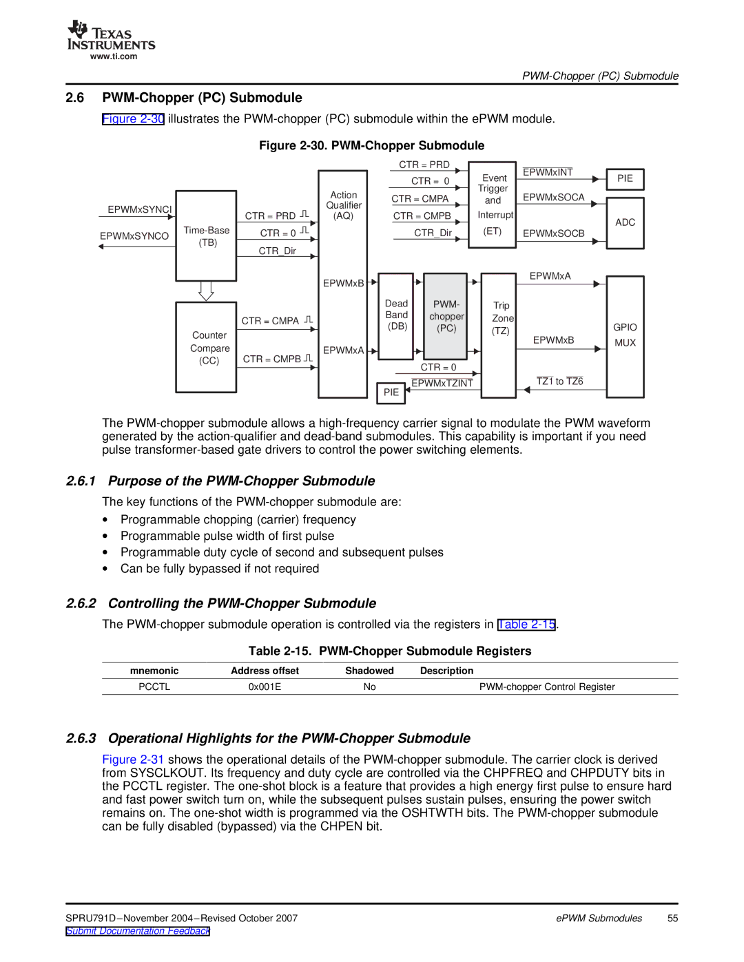
Figure 2-30 illustrates the PWM-chopper (PC) submodule within the ePWM module.
Figure 2-30. PWM-Chopper Submodule
EPWMxSYNCI
EPWMxSYNCO
(TB)
Counter
Compare
(CC)
CTR = PRD ![]()
![]()
CTR = 0 ![]()
![]()
CTR_Dir
CTR = CMPA
CTR = CMPB ![]()
![]()
|
|
| CTR = PRD | Event |
|
|
| CTR = 0 | |
|
|
| Trigger | |
Action |
| CTR = CMPA | ||
| and | |||
Qualifier |
| |||
|
|
| Interrupt | |
(AQ) |
|
| CTR = CMPB | |
|
|
| CTR_Dir | (ET) |
|
|
|
|
|
EPWMxB |
|
|
Dead | PWM- | Trip |
Band | chopper | Zone |
(DB) | (PC) | (TZ) |
EPWMxA |
|
|
| CTR = 0 |
|
PIE | EPWMxTZINT |
|
|
|
EPWMxINT
EPWMxSOCA
EPWMxSOCB
EPWMxA
EPWMxB
TZ1 to TZ6
PIE
ADC
GPIO MUX
The
2.6.1 Purpose of the PWM-Chopper Submodule
The key functions of the
∙Programmable chopping (carrier) frequency
∙Programmable pulse width of first pulse
∙Programmable duty cycle of second and subsequent pulses
∙Can be fully bypassed if not required
2.6.2Controlling the PWM-Chopper Submodule
The
Table 2-15. PWM-Chopper Submodule Registers
mnemonic | Address offset | Shadowed | Description |
PCCTL | 0x001E | No |
2.6.3 Operational Highlights for the PWM-Chopper Submodule
Figure 2-31 shows the operational details of the PWM-chopper submodule. The carrier clock is derived from SYSCLKOUT. Its frequency and duty cycle are controlled via the CHPFREQ and CHPDUTY bits in the PCCTL register. The one-shot block is a feature that provides a high energy first pulse to ensure hard and fast power switch turn on, while the subsequent pulses sustain pulses, ensuring the power switch remains on. The one-shot width is programmed via the OSHTWTH bits. The PWM-chopper submodule can be fully disabled (bypassed) via the CHPEN bit.
ePWM Submodules | 55 |