2.The following message should display on the terminal screen once the module is installed properly and the
Ethernet Management Module (v4.00), Copyright (c) 1993
Chipcom Corporation
The EMM Front Panel
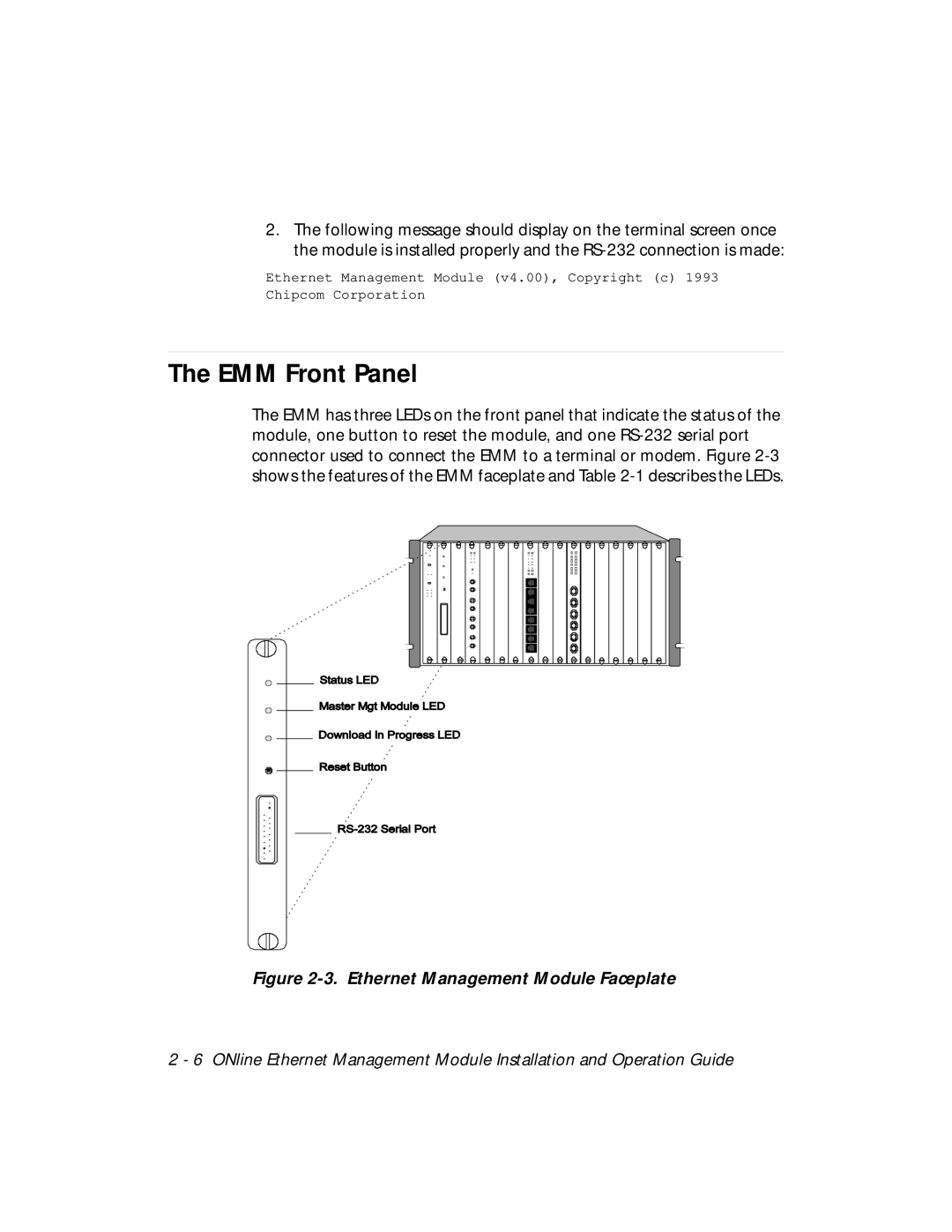
The EMM has three LEDs on the front panel that indicate the status of the module, one button to reset the module, and one
Figure 2-3. Ethernet Management Module Faceplate
2 - 6 ONline Ethernet Management Module Installation and Operation Guide