166 | Appendix B: Memory configuration |
The memory boards connect to the mainboard through the memory board slots A, B, C, and D (Each slot support the x16 PCI Express mechanical slot, refer to “Mainboard” on page 12 for the location of the memory board slots.). Each memory board is equipped with eight DIMM slots that supports 1 GB, 2 GB, or 4 GB
Refer to “Memory configuration” on page 171 for details on the available system memory configuration.
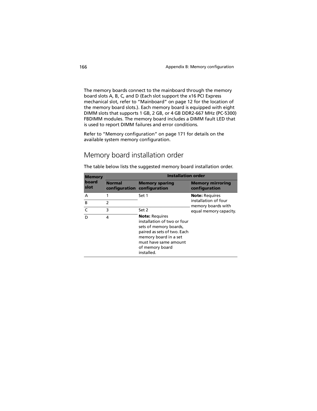
Memory board installation order
The table below lists the suggested memory board installation order.
Memory |
| Installation order | |
board | Normal | Memory sparing | Memory mirroring |
slot | configuration | configuration | configuration |
|
|
|
|
A | 1 | Set 1 |
|
|
|
B | 2 |
|
|
|
|
C | 3 | Set 2 |
|
| Note: Requires |
D | 4 |
installation of two or four sets of memory boards, paired as sets of two. Each memory board in a set must have same amount of memory board installed.
Note: Requires installation of four memory boards with equal memory capacity.