Chapter 5 Theory of Operation
Output Attenuator
Output Attenuator
Block 8 on block diagram page 129; Schematic on page 138.
The Output Attenuator provides 0 to 30 dB of signal attenuation between the output amplifier section and the output BNC connector. Output signal levels are controlled by combining coarse amplitude control from the output attenuator section and
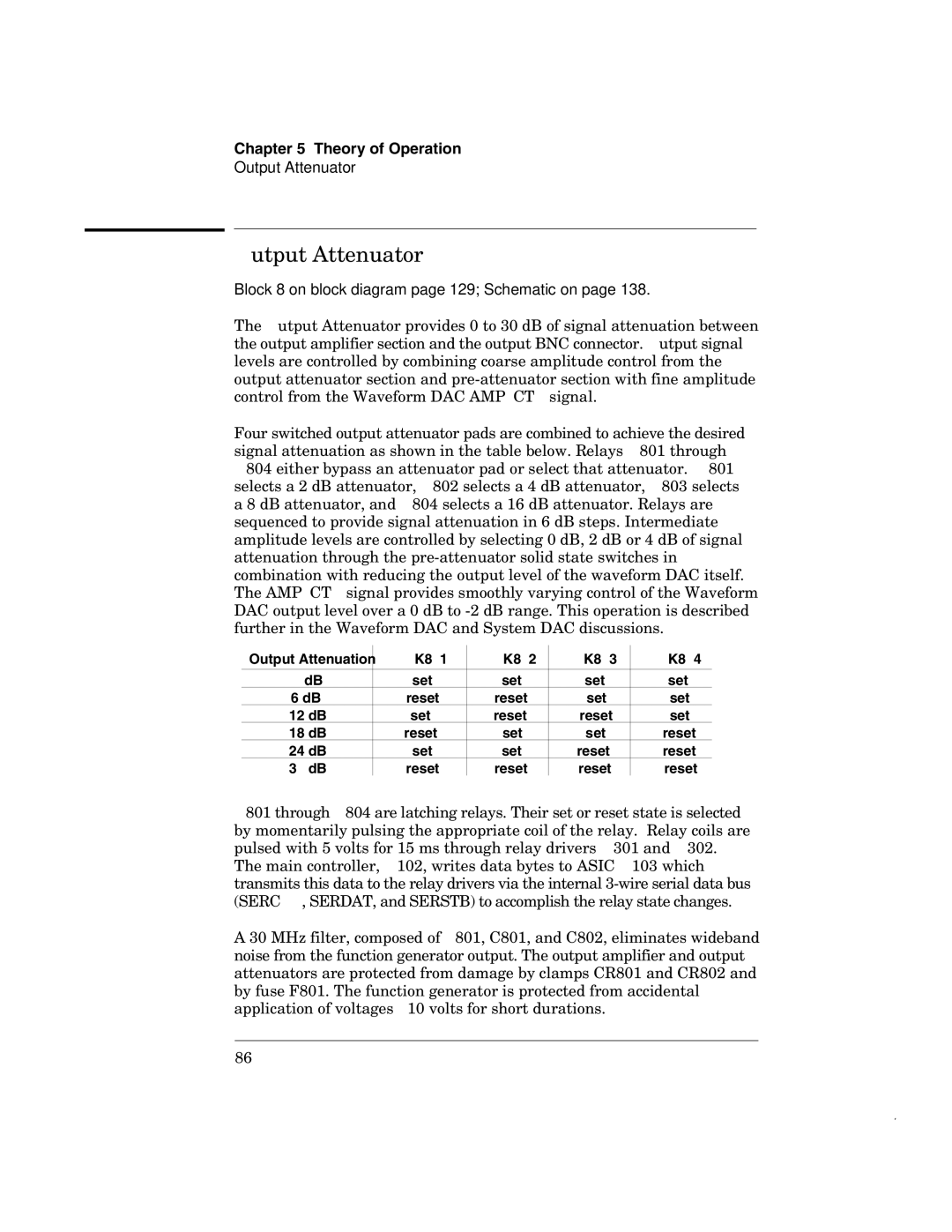
Four switched output attenuator pads are combined to achieve the desired signal attenuation as shown in the table below. Relays K801 through K804 either bypass an attenuator pad or select that attenuator. K801 selects a 2 dB attenuator, K802 selects a 4 dB attenuator, K803 selects a 8 dB attenuator, and K804 selects a 16 dB attenuator. Relays are sequenced to provide signal attenuation in 6 dB steps. Intermediate amplitude levels are controlled by selecting 0 dB, 2 dB or 4 dB of signal attenuation through the
Output Attenuation | K801 | K802 | K803 | K804 |
|
|
|
|
|
0 dB | set | set | set | set |
6 dB | reset | reset | set | set |
12 dB | set | reset | reset | set |
18 dB | reset | set | set | reset |
24 dB | set | set | reset | reset |
30 dB | reset | reset | reset | reset |
K801 through K804 are latching relays. Their set or reset state is selected by momentarily pulsing the appropriate coil of the relay. Relay coils are pulsed with 5 volts for 15 ms through relay drivers U301 and U302. The main controller, U102, writes data bytes to ASIC U103 which transmits this data to the relay drivers via the internal
A 30 MHz filter, composed of L801, C801, and C802, eliminates wideband noise from the function generator output. The output amplifier and output attenuators are protected from damage by clamps CR801 and CR802 and by fuse F801. The function generator is protected from accidental application of voltages <10 volts for short durations.
86