Chapter 4 Calibration Procedures
Automating Calibration Procedures
Automating Calibration Procedures
You can automate the complete verification and adjustment procedures outlined in this chapter if you have access to programmable test equipment. You can program the instrument configurations specified for each test over the remote interface. You can then enter readback verification data into a test program and compare the results to the appropriate test limit values.
You can also enter calibration constants from the remote interface. Remote operation is similar to the local
Recommended Test Equipment
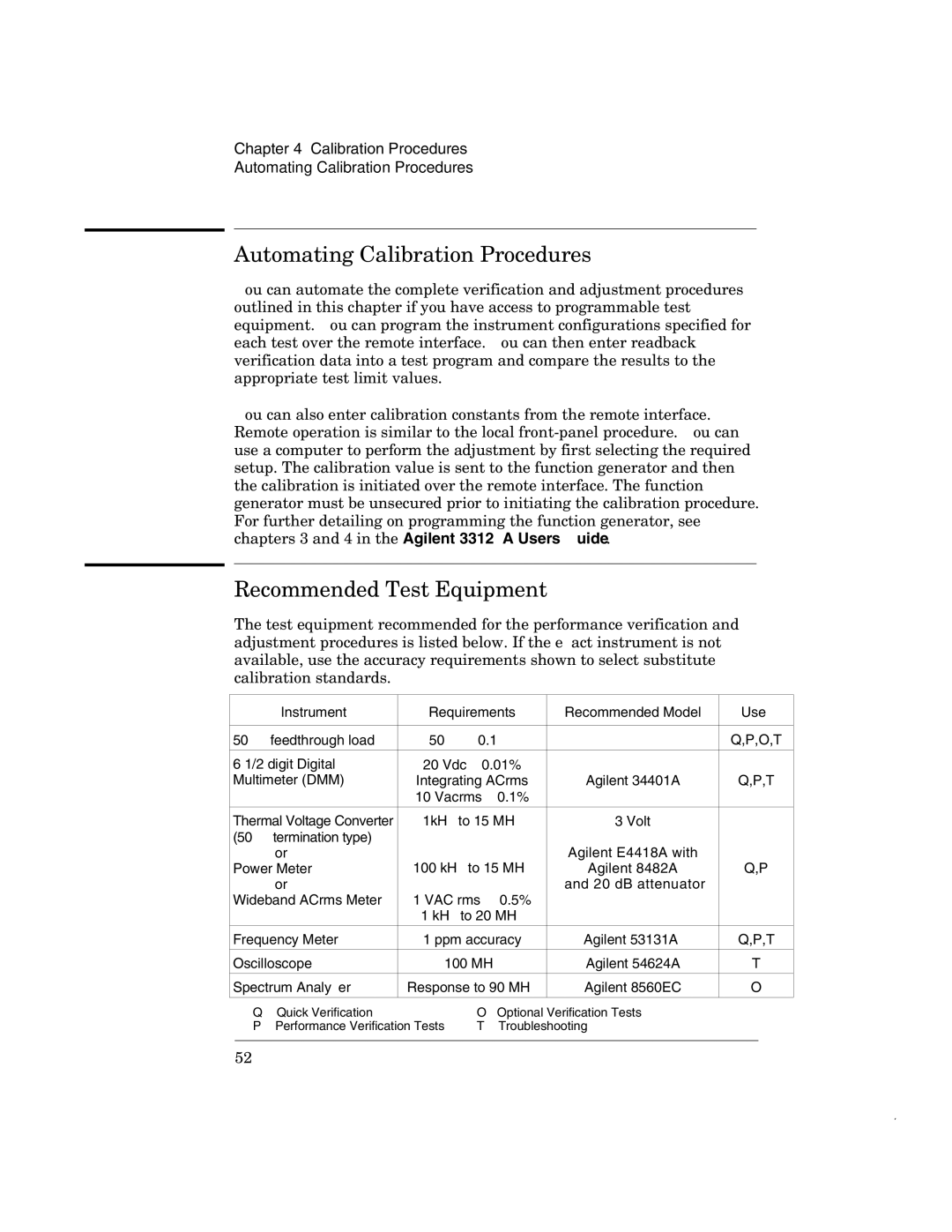
The test equipment recommended for the performance verification and adjustment procedures is listed below. If the exact instrument is not available, use the accuracy requirements shown to select substitute calibration standards.
Instrument | Requirements | Recommended Model | Use* |
|
|
|
|
50 W feedthrough load | 50 W – 0.1 W |
| Q,P,O,T |
|
|
|
|
6 1/2 digit Digital | 20 Vdc – 0.01% |
|
|
Multimeter (DMM) | Integrating ACrms | Agilent 34401A | Q,P,T |
| 10 Vacrms – 0.1% |
|
|
|
|
|
|
Thermal Voltage Converter | 1kHz to 15 MHz | 3 Volt |
|
(50 W termination type) |
| Agilent E4418A with |
|
or | 100 kHz to 15 MHz |
| |
Power Meter | Agilent 8482A | Q,P | |
or | 1 VAC rms – 0.5% | and 20 dB attenuator |
|
Wideband ACrms Meter | — |
| |
| 1 kHz to 20 MHz |
|
|
Frequency Meter | 1 ppm accuracy | Agilent 53131A | Q,P,T |
|
|
|
|
Oscilloscope | 100 MHz | Agilent 54624A | T |
|
|
|
|
Spectrum Analyzer | Response to 90 MHz | Agilent 8560EC | O |
|
|
|
|
* Q = Quick Verification | O= Optional Verification Tests |
P = Performance Verification Tests | T = Troubleshooting |
|
|
52