3 - Installation
Control Connector
A
Consistent with good engineering practice, all leads connected to the control connector should be twisted and shielded to maintain the instrument's specified performance. Make all wire connections to the mating plug as required before installing the connector in the module.
| Not available | ||
A4 | Provides the common connection for the A5 and A6 pins. | ||
A5 | A | ||
| programmed ON. This signal can be used to control an external device such as a relay for | ||
| shorting or disconnecting the module's input terminals or as a general purpose digital output | ||
| port. This signal powers up in the inactive | ||
A6 | A | ||
| reverse voltage condition or fault occurs. This signal powers up in the inactive | ||
A7 | Provides the common connection for the external programming input (pin A8). | ||
A8 | Connects an external programming input. The CC and CV mode can be programmed with a | ||
| |||
| programmed over the GPIB or | ||
| dc level. | ||
A9 | Provides the common connection for the current and voltage monitor signals (pins A10 and | ||
| A11). | ||
A11 and A10 | Used to monitor the modules input current and voltage. A | ||
| pin indicates the | ||
| monitors voltage. | ||
+S and | Used to connect the remote sense leads to the power source. Pin +S connects the +S signal and | ||
| pin | ||
|
|
|
|
|
|
|
|
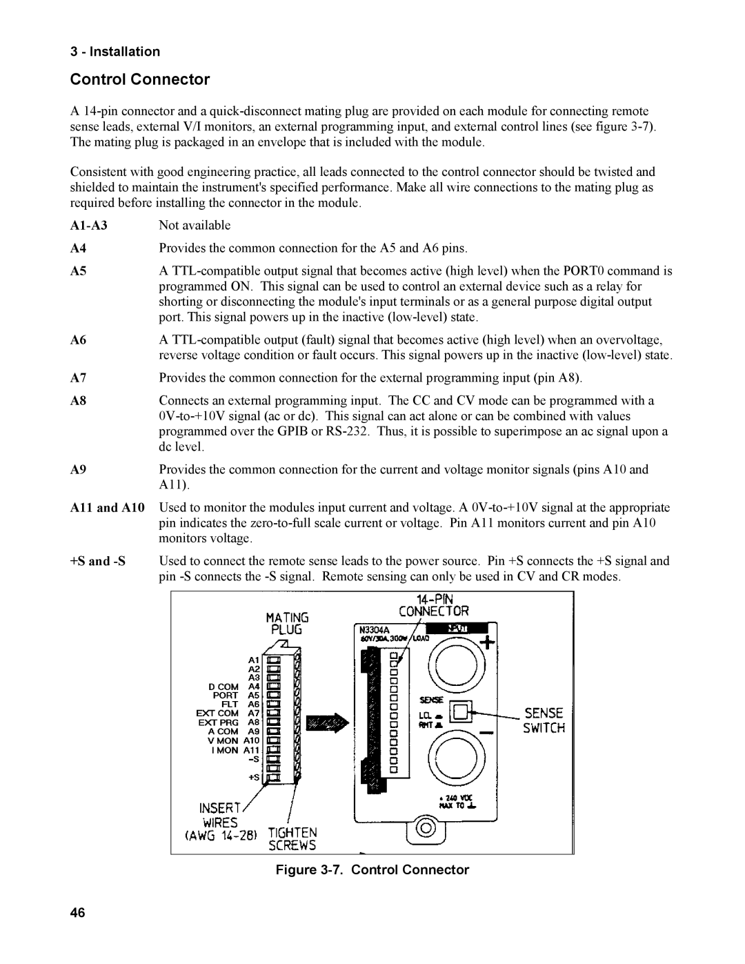
Figure 3-7. Control Connector
46