3 - Installation
Computer Connections
The electronic load can be controlled through a GPIB interface or through an
GPIB Interface
Each electronic load has its own GPIB bus address, which can be set using the front panel Address key as described in Chapter 5. GPIB address data is stored in a
Electronic loads may be connected to the GPIB interface in series configuration, star configuration, or a combination of the two, provided the following rules are observed:
♦The total number of devices including the GPIB interface card is no more than 15.
♦The total length of all cables used is no more than 2 meters times the number of devices connected together, up to a maximum of 20 meters. (Refer to Table
♦Do not stack more than three connector blocks together on any GPIB connector.
♦Make sure all connectors are fully seated and the lock screws are firmly
RS-232 Interface
The electronic loads have an
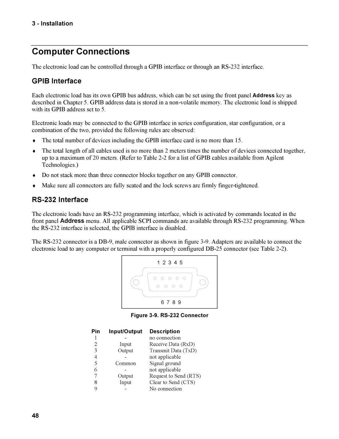
The
1 2 3 4 5 |
6 7 8 9 |
Figure |
Pin | Input/Output | Description |
1 | - | no connection |
2 | Input | Receive Data (RxD) |
3 | Output | Transmit Data (TxD) |
4 | - | not applicable |
5 | Common | Signal ground |
6 | - | not applicable |
7 | Output | Request to Send (RTS) |
8 | Input | Clear to Send (CTS) |
9 | - | No connection |
48