General Information - 2
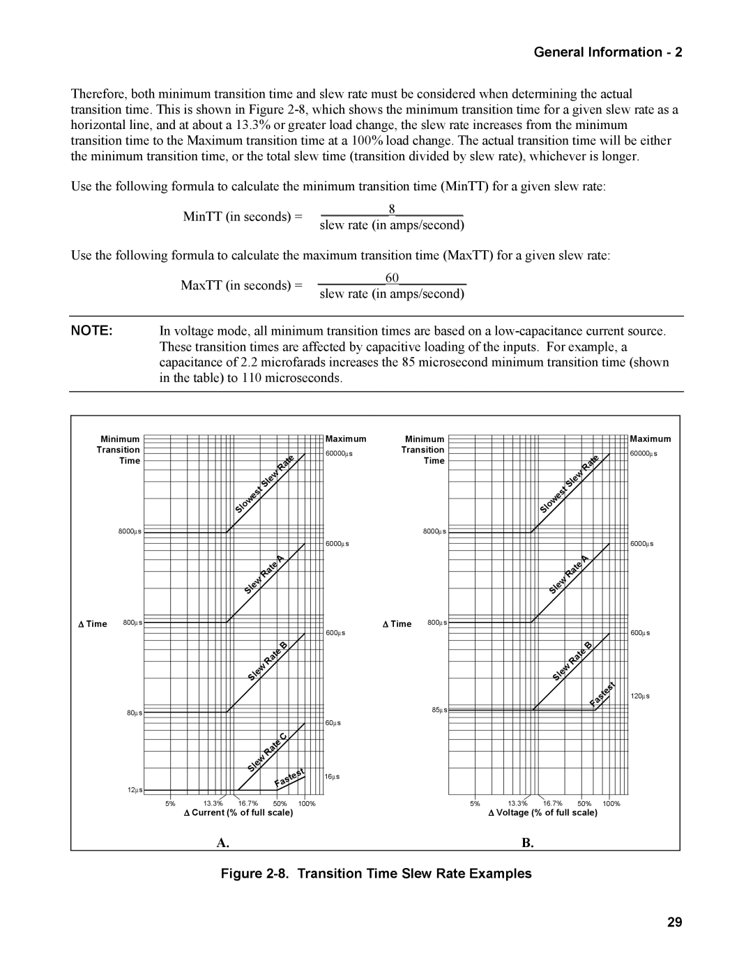
Therefore, both minimum transition time and slew rate must be considered when determining the actual transition time. This is shown in Figure
Use the following formula to calculate the minimum transition time (MinTT) for a given slew rate:
MinTT (in seconds) = | __________8__________ | |
slew rate (in amps/second) | ||
|
Use the following formula to calculate the maximum transition time (MaxTT) for a given slew rate:
MaxTT (in seconds) = | __________60__________ | |
slew rate (in amps/second) | ||
|
NOTE: In voltage mode, all minimum transition times are based on a
Minimum |
|
|
|
|
|
|
|
|
|
| Maximum | Minimum | |||
Transition |
|
|
|
|
|
|
|
|
|
| 60000 | ∝ | Transition | ||
| Time |
|
|
|
| Rate |
|
| s |
| Time | ||||
|
|
|
|
|
|
|
|
|
| ||||||
|
|
|
|
| lew |
|
|
|
|
|
| ||||
|
|
|
|
|
|
|
|
|
|
|
|
|
|
| |
|
|
| est | S |
|
|
|
|
|
|
|
|
|
| |
|
|
|
|
|
|
|
|
|
|
|
|
|
|
| |
|
|
| w |
|
|
|
|
|
|
|
|
|
|
|
|
|
|
| lo |
|
|
|
|
|
|
|
|
|
|
|
|
|
|
| S |
|
|
|
|
|
|
|
|
|
|
|
|
| 8000∝ s |
|
|
|
|
|
|
|
|
|
|
|
|
| 8000∝ s |
|
|
|
|
|
|
|
|
|
|
|
| 6000∝ s |
|
| |
|
|
|
|
| e | A |
|
|
|
|
|
|
|
| |
|
|
|
|
|
|
|
|
|
|
|
|
|
|
| |
|
|
| lew | Rat |
|
|
|
|
|
|
|
|
|
| |
|
|
|
|
|
|
|
|
|
|
|
|
|
|
| |
|
|
| S |
|
|
|
|
|
|
|
|
|
|
|
|
∆ Time | 800∝ s |
|
|
|
|
|
|
|
|
|
| 600∝ s |
| ∆ Time | 800∝ s |
|
|
|
|
|
|
|
|
|
|
|
|
|
|
| |
|
|
|
|
| Rate | B |
|
|
|
|
|
|
| ||
|
|
| Slew |
|
|
|
|
|
|
|
|
| |||
|
|
|
|
|
|
|
|
|
|
|
|
|
| ||
| 80∝ s |
|
|
|
|
|
|
|
|
|
|
|
|
| 85∝ s |
|
|
|
|
|
|
|
|
|
|
|
|
|
|
| |
|
|
|
|
|
|
|
|
|
|
|
| 60∝ s |
|
|
|
|
|
|
|
| e | C |
|
|
|
|
|
|
| ||
|
|
|
|
|
|
|
|
|
|
|
|
|
| ||
|
|
| lew | Rat |
|
|
|
|
|
|
|
|
|
| |
|
|
|
|
|
|
|
|
| t |
|
|
|
| ||
|
|
| S |
|
|
|
|
|
|
|
|
|
|
| |
|
|
|
|
|
|
|
|
|
| s | 16∝ s |
|
|
| |
|
|
|
|
|
|
|
|
| te |
|
|
|
| ||
|
|
|
|
|
|
|
| s |
|
|
|
|
|
| |
|
|
|
|
|
| a |
|
|
|
|
|
|
| ||
| 12∝ s |
|
|
| F |
|
|
|
|
|
|
|
| ||
|
|
|
|
|
|
|
|
|
|
|
|
|
|
| |
| 5% | 13.3% | 16.7% |
| 50% |
| 100% |
|
|
|
| ||||
∆Current (% of full scale)
|
|
|
|
|
|
|
| Maximum |
|
|
|
|
| Rate |
| 60000∝ s | |
|
|
|
| lew |
|
| ||
|
|
|
|
|
|
|
| |
|
| est | S |
|
|
|
| |
|
|
|
|
|
|
|
| |
|
| w |
|
|
|
|
|
|
|
| lo |
|
|
|
|
|
|
|
| S |
|
|
|
|
|
|
|
|
|
|
|
|
|
| 6000∝ s |
|
|
|
| e | A |
|
| |
|
|
|
|
|
|
|
| |
|
| lew | Rat |
|
|
|
| |
|
|
|
|
|
|
|
| |
|
| S |
|
|
|
|
|
|
|
|
|
|
|
|
|
| 600∝ s |
|
|
|
| Rate | B |
|
| |
|
| Slew |
|
|
| |||
|
|
|
| astest |
| |||
|
|
|
|
|
| 120∝ s | ||
|
|
|
|
|
|
| ||
|
|
|
|
|
| F |
|
|
5% | 13.3% | 16.7% |
| 50% | 100% |
| ||
∆Voltage (% of full scale)
A.B.
Figure 2-8. Transition Time Slew Rate Examples
29