2 - General Information
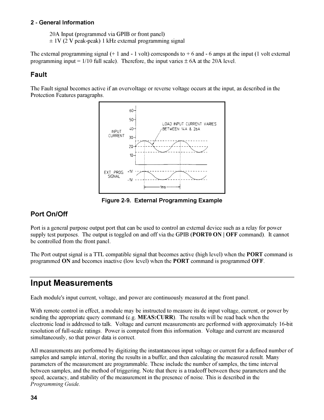
20A Input (programmed via GPIB or front panel)
± 1V (2 V
The external programming signal (+ 1 and - 1 volt) corresponds to + 6 and - 6 amps at the input (1 volt external programming input = 1/10 full scale). Therefore, the input varies ± 6A at the 20A level.
Fault
The Fault signal becomes active if an overvoltage or reverse voltage occurs at the input, as described in the Protection Features paragraphs.
Figure 2-9. External Programming Example
Port On/Off
Port is a general purpose output port that can be used to control an external device such as a relay for power supply test purposes. The output is toggled on and off via the GPIB (PORT0 ON OFF command). It cannot be controlled from the front panel.
The Port output signal is a TTL compatible signal that becomes active (high level) when the PORT command is programmed ON and becomes inactive (low level) when the PORT command is programmed OFF.
Input Measurements
Each module's input current, voltage, and power are continuously measured at the front panel.
With remote control in effect, a module may be instructed to measure its dc input voltage, current, or power by sending the appropriate query command (e.g. MEAS:CURR). The results will be read back when the electronic load is addressed to talk. Voltage and current measurements are performed with approximately
All measurements are performed by digitizing the instantaneous input voltage or current for a defined number of samples and sample interval, storing the results in a buffer, and then calculating the measured result. Many parameters of the measurement are programmable. These include the number of samples, the time interval between samples, and the method of triggering. Note that there is a tradeoff between these parameters and the speed, accuracy, and stability of the measurement in the presence of noise. This is described in the Programming Guide.
34