Installation - 3

In Figure 3-12, all lead connections are terminated at the source. Each module is connected to the source using separate wires. Using the source as the current distribution point allows larger wires to be used for each module connection and also reduces the common impedance inherent in daisy-chained configurations.

If because of lead length or other considerations, lead connections cannot be made at the source, a remote distribution terminal may be required. Lead connections can also be daisy-chained across the module input connectors as long as the total current draw is less than the ampere-rating of AWG 8 wire (see Table 3-2). This is because two wires larger than AWG 8 cannot both fit inside the module input connectors.

Low Voltage Operation

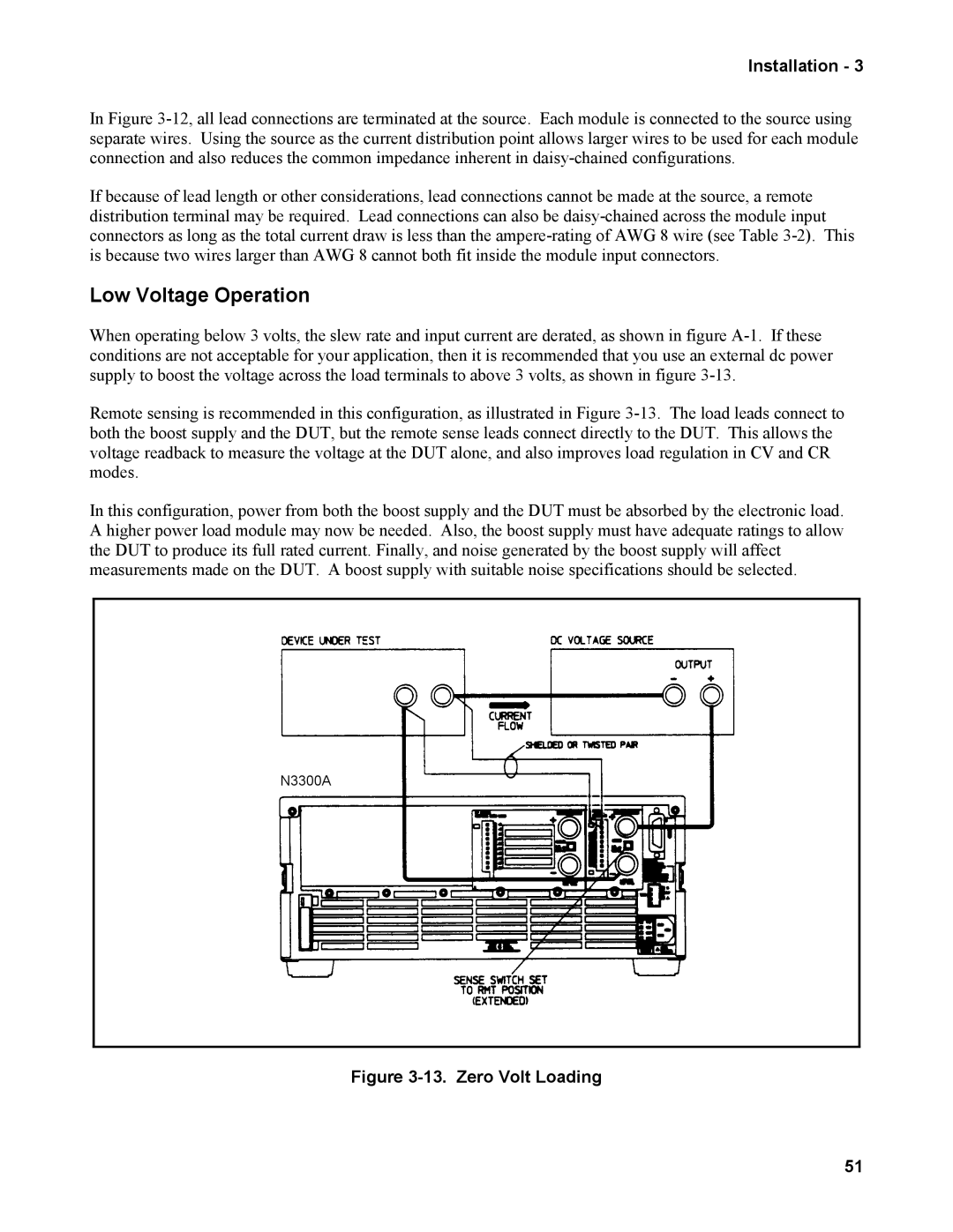
When operating below 3 volts, the slew rate and input current are derated, as shown in figure A-1. If these conditions are not acceptable for your application, then it is recommended that you use an external dc power supply to boost the voltage across the load terminals to above 3 volts, as shown in figure 3-13.

Remote sensing is recommended in this configuration, as illustrated in Figure 3-13. The load leads connect to both the boost supply and the DUT, but the remote sense leads connect directly to the DUT. This allows the voltage readback to measure the voltage at the DUT alone, and also improves load regulation in CV and CR modes.

In this configuration, power from both the boost supply and the DUT must be absorbed by the electronic load. A higher power load module may now be needed. Also, the boost supply must have adequate ratings to allow the DUT to produce its full rated current. Finally, and noise generated by the boost supply will affect measurements made on the DUT. A boost supply with suitable noise specifications should be selected.

N3300A

Figure 3-13. Zero Volt Loading

51

Page 49
Image 49
Agilent Technologies n3305a, n3304a, n3301a, n3303a, n3306a, n3302a, n3300a manual Low Voltage Operation, Zero Volt Loading