4
Turn-On Checkout
Introduction
Successful tests in this chapter provide a high degree of confidence that the electronic load is operating properly. For verification tests, see Appendix B.
NOTE: This chapter provides a preliminary introduction to the electronic load front panel. See Chapter 5 for more detail.
Checkout Procedure
The tests in this section checks for proper operation of the electronic load. If you have not already done so, connect the power cord to the unit and plug it in.
The following procedure assumes that the unit turns in the
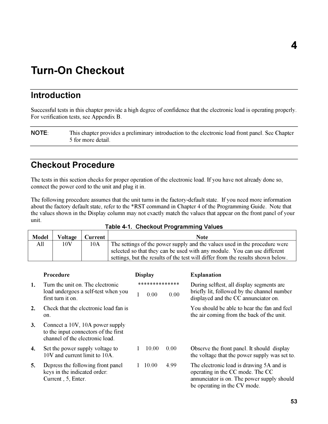
Table 4-1. Checkout Programming Values
Model | Voltage | Current | Note |
All | 10V | 10A | The settings of the power supply and the values used in the procedure were |
|
|
| selected so that they can be used with any module. You can use different |
|
|
| settings, but the results of the test will differ from the results shown below. |
Procedure
1.Turn the unit on. The electronic load undergoes a
2.Check that the electronic load fan is on.
3.Connect a 10V, 10A power supply to the input connectors of the first channel of the electronic load.
4.Set the power supply voltage to 10V and current limit to 10A.
5.Depress the following front panel keys in the indicated order: Current , 5, Enter.
Display
**************
1 0.00 0.00
1 10.00 0.00
1 10.00 4.99
Explanation
During selftest, all display segments are briefly lit, followed by the channel number displayed and the CC annunciator on.
You should be able to hear the fan and feel the air coming from the back of the unit.
Observe the front panel. It should display the voltage that the power supply was set to.
The electronic load is drawing 5A and is operating in the CC mode. The CC annunciator is on. The power supply should be operating in the CV mode.
53
