SwitchBlade x3112 Installation Guide
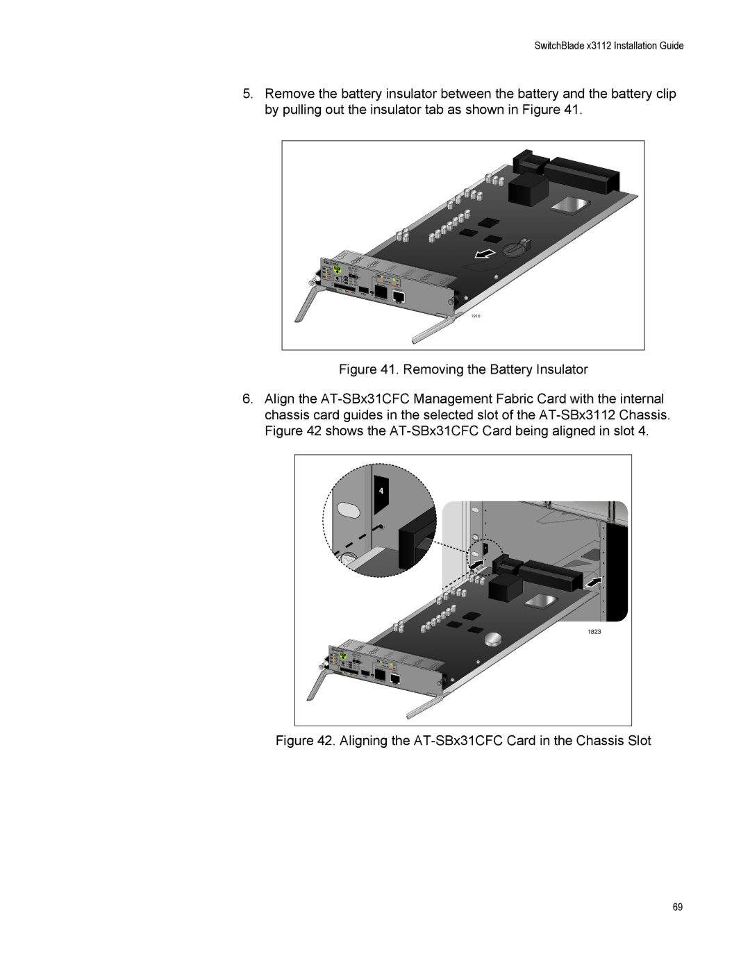
5.Remove the battery insulator between the battery and the battery clip by pulling out the insulator tab as shown in Figure 41.
SBx31CFC |
|
|
|
|
|
|
| |
SYS | STATUS |
| SBx |
|
|
|
|
|
M/S |
|
|
|
|
|
| ||
| SLMASTER |
| 0STATUS |
|
|
|
| |
PSU | AVE |
| 2 | 1 |
|
|
|
|
| NORMAL |
| 3 |
|
|
|
| |
| FAULT |
| 4 |
|
|
|
| |
FAN | NORMAL | M/S | 5 | CFC | 1000 | LINK | ||
| FAULT | PSU | 6 | 7 |
|
| ||
| RESET | 8 | 9 |
| 10/100 | ACT | ||
|
| FAN | 10 |
| LINK | |||
|
| SD | 11 |
| NET MGMT |
| ACT | |
| READY | BUSY |
|
|
|
|
| CONSOLE |
|
|
| FAULT |
|
| L/A |
|
|
|
|
|
|
|
|
| ||
|
|
|
|
|
|
|
| |
|
|
|
|
|
|
|
| 1916 |
Figure 41. Removing the Battery Insulator
6.Align the AT-SBx31CFC Management Fabric Card with the internal chassis card guides in the selected slot of the AT-SBx3112 Chassis. Figure 42 shows the AT-SBx31CFC Card being aligned in slot 4.
|
|
|
|
|
| 4 |
|
|
|
|
|
|
|
|
|
| 2 |
|
|
|
|
|
|
|
| 4 |
|
|
|
|
|
| 6 |
| 6 |
|
|
|
|
|
|
|
| |
|
|
|
|
|
|
|
| 8 |
|
|
|
|
|
|
|
| 10 |
|
|
|
|
|
|
|
| 1823 |
SBx31CFC |
|
|
|
|
|
|
|
|
SYS STATUS |
| SBx | STATUS |
|
|
|
| |
MASTER |
| 0 |
|
|
|
| ||
SLAVE |
|
| 1 |
|
|
|
| |
NORMAL |
| 2 |
| 3 |
|
|
|
|
FAULT |
| 4 |
|
|
|
|
| |
NORMAL | M/S |
| 5 | CFC | 1000 LINK |
| ||
FAULT | 6 |
| 7 | ACT | ||||
RESET | PSU | 8 |
|
| 10/100 | LINK | ||
FAN |
| 9 |
| ACT | ||||
| 10 |
|
| NET MGMT | ||||
| SD |
|
| 11 |
|
| ||
READY | BUSY | FAULT |
|
| L/A |
| CONSOLE | |
|
|
|
|
|
| |||
|
|
|
|
|
|
|
| |
|
|
|
|
|
|
|
| |
Figure 42. Aligning the AT-SBx31CFC Card in the Chassis Slot
69