Appendix A: Technical Specifications
Connectors and Port Pinouts
This section lists the connectors and connector pinouts for the
SwitchBlade x3112 line cards.
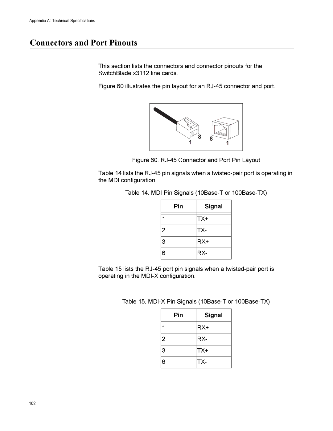
Figure 60 illustrates the pin layout for an RJ-45 connector and port.
8 | 8 | 1 |
1 |
|
Figure 60. RJ-45 Connector and Port Pin Layout
Table 14 lists the RJ-45 pin signals when a twisted-pair port is operating in the MDI configuration.
Table 14. MDI Pin Signals (10Base-T or 100Base-TX)
Pin | Signal |
|
|
|
|
1 | TX+ |
|
|
2 | TX- |
|
|
3 | RX+ |
|
|
6 | RX- |
|
|
Table 15 lists the
Table 15.
Pin | Signal |
|
|
|
|
1 | RX+ |
|
|
2 | RX- |
|
|
3 | TX+ |
|
|
6 | TX- |
|
|
102