SwitchBlade x3112 Installation Guide
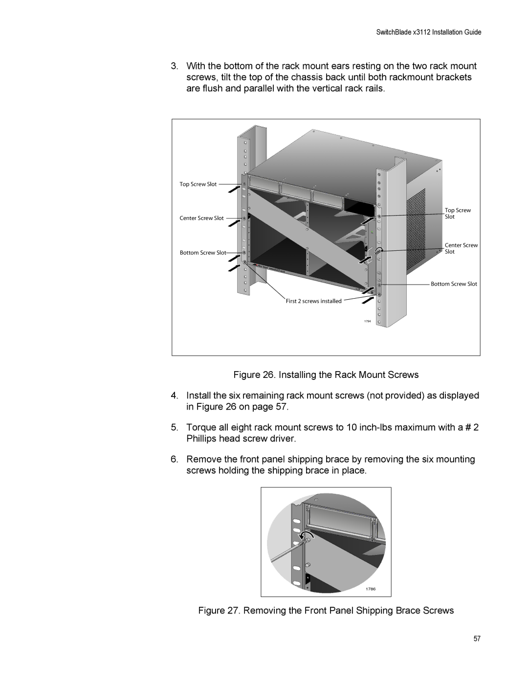
3.With the bottom of the rack mount ears resting on the two rack mount screws, tilt the top of the chassis back until both rackmount brackets are flush and parallel with the vertical rack rails.
| P |
|
|
| O |
|
|
| E |
|
|
Top Screw Slot |
| P |
|
| O |
| |
| E |
| |
| 0 |
|
|
|
| S |
|
|
| Y |
|
|
| S |
|
|
| T |
|
| 2 | E |
|
| M |
| |
|
| S |
|
|
| Y | Top Screw |
|
| S | |
|
| T | |
|
| E | |
|
| M | |
|
|
| |
Center Screw Slot | 4 |
| Slot |
| 31FAN | ||
|
| 1 |
|
| 6 |
|
|
|
| 3 |
|
| 8 |
|
|
|
| 5 | Center Screw |
Bottom Screw Slot |
| Slot | |
10 |
| ||
|
| ||
|
| 7 |
|
|
| 9 |
|
|
| 11 | Bottom Screw Slot |
|
| ESD |
|
|
| First 2 screws installed |
|
|
| 1794 |
|
Figure 26. Installing the Rack Mount Screws
4.Install the six remaining rack mount screws (not provided) as displayed in Figure 26 on page 57.
5.Torque all eight rack mount screws to 10 inch-lbs maximum with a # 2 Phillips head screw driver.
6.Remove the front panel shipping brace by removing the six mounting screws holding the shipping brace in place.
P |
O |
E |
P |
O |
E |
0 |
2 |
4 |
1786 |
Figure 27. Removing the Front Panel Shipping Brace Screws
57