Chapter 2: Installation
Installing an XFP Transceiver
To install an XFP transceiver in the
1.Remove the dust plug from a transceiver slot on the switch. Refer to Figure 52.
|
|
|
|
| 3 |
SBx31XZ4 |
|
|
|
|
|
0 |
| PORT | ACTIVITY |
|
|
|
| 10G |
|
| |
|
| LINK / |
| 5 | |
|
|
| ACT | ||
| 1 |
|
| ||
|
|
|
| ||
XFP |
|
|
|
| 2 |
|
|
|
|
| |
| XFP |
|
|
| 3 |
|
|
|
|
| XFP |
|
|
|
|
| XFP |
|
|
|
|
| 7 |
Figure 52. Removing an XFP Dust Plug
2.Remove the transceiver from its shipping container and store the packaging material in a safe location.
3.Position the transceiver with the label facing down.
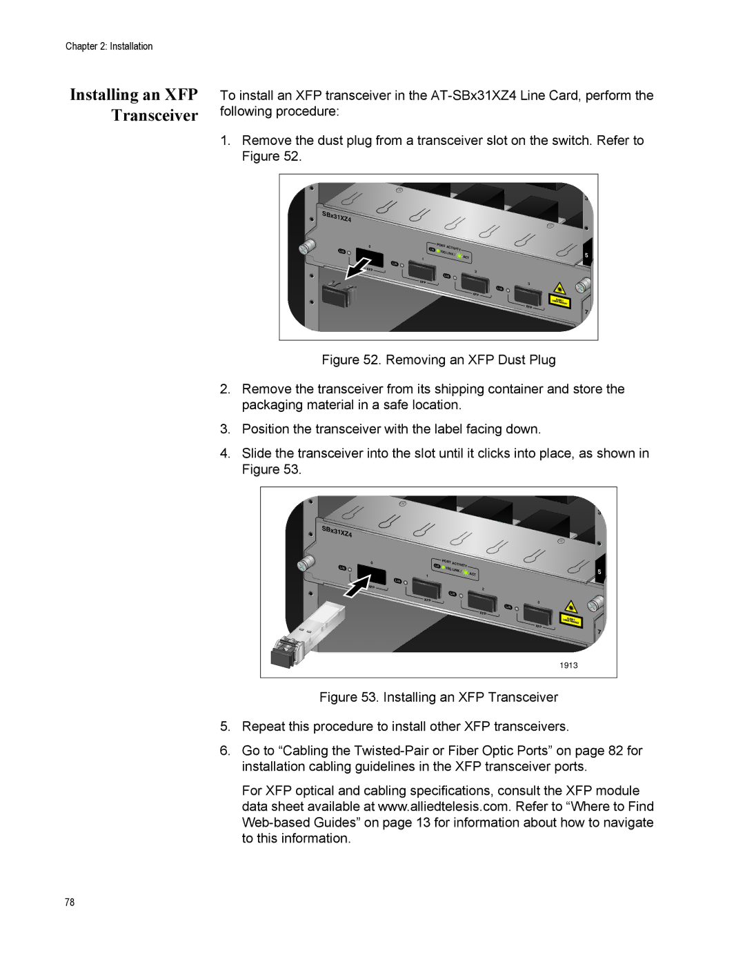
4.Slide the transceiver into the slot until it clicks into place, as shown in Figure 53.
|
|
|
|
| 3 |
SBx31XZ4 |
|
|
|
|
|
0 |
| PORT | ACTIVITY |
|
|
|
| 10G |
|
| |
|
| LINK / |
| 5 | |
|
|
| ACT | ||
| 1 |
|
| ||
XFP |
|
|
|
| 2 |
|
|
|
|
| |
| XFP |
|
|
| 3 |
|
|
|
|
| |
|
|
|
|
| XFP |
|
|
|
|
| XFP |
|
|
|
|
| 7 |
|
|
|
|
| 1913 |
Figure 53. Installing an XFP Transceiver
5.Repeat this procedure to install other XFP transceivers.
6.Go to “Cabling the Twisted-Pair or Fiber Optic Ports” on page 82 for installation cabling guidelines in the XFP transceiver ports.
For XFP optical and cabling specifications, consult the XFP module data sheet available at www.alliedtelesis.com. Refer to “Where to Find
78