Chapter 1: Overview
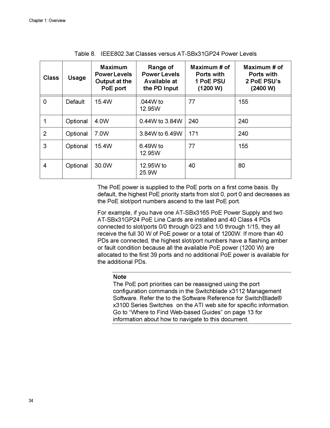
Table 8. IEEE802.3at Classes versus
|
| Maximum | Range of | Maximum # of | Maximum # of | ||
Class | Usage | Power Levels | Power Levels | Ports with | Ports with | ||
Output at the | Available at | 1 | PoE PSU | 2 PoE PSU’s | |||
|
| ||||||
|
| PoE port | the PD Input | (1200 W) | (2400 W) | ||
|
|
|
|
|
|
| |
|
|
|
|
|
|
| |
0 | Default | 15.4W | .044W to | 77 |
| 155 | |
|
|
| 12.95W |
|
|
| |
|
|
|
|
|
|
| |
1 | Optional | 4.0W | 0.44W to 3.84W | 240 |
| 240 | |
|
|
|
|
|
|
| |
2 | Optional | 7.0W | 3.84W to 6.49W | 171 |
| 240 | |
|
|
|
|
|
|
| |
3 | Optional | 15.4W | 6.49W to | 77 |
| 155 | |
|
|
| 12.95W |
|
|
| |
|
|
|
|
|
|
| |
4 | Optional | 30.0W | 12.95W to | 40 |
| 80 | |
|
|
| 25.9W |
|
|
| |
|
|
|
|
|
|
| |
The PoE power is supplied to the PoE ports on a first come basis. By default, the highest PoE priority starts from slot 0, port 0 and decreases as the PoE slot/port numbers ascend to the last PoE port.
For example, if you have one
Note
The PoE port priorities can be reassigned using the port configuration commands in the Switchblade x3112 Management Software. Refer the to the Software Reference for SwitchBlade® x3100 Series Switches on the ATI web site for specific information. Go to “Where to Find
34