SwitchBlade x3112 Installation Guide
Port LED is Off on AT-SBx31XZ4 XFP Line Card
For fiber optic uplink ports that have an XFP transceiver installed, verify that the 1000 LINK LED is ON. If a 1000 LINK LED is off but the transceiver is present, do the following:
Verify that the end node connected to the port is powered ON and is operating properly.
Check that the fiber optic cable is securely connected to the XFP transceiver in the
1858 |
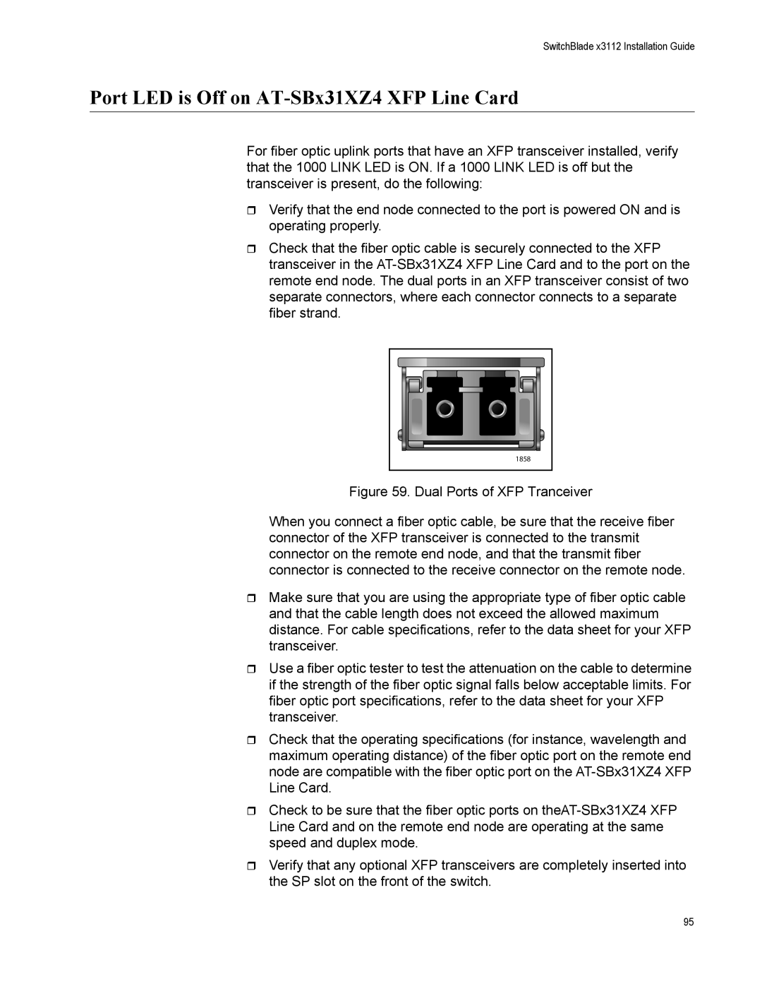
Figure 59. Dual Ports of XFP Tranceiver
When you connect a fiber optic cable, be sure that the receive fiber connector of the XFP transceiver is connected to the transmit connector on the remote end node, and that the transmit fiber connector is connected to the receive connector on the remote node.
Make sure that you are using the appropriate type of fiber optic cable and that the cable length does not exceed the allowed maximum distance. For cable specifications, refer to the data sheet for your XFP transceiver.
Use a fiber optic tester to test the attenuation on the cable to determine if the strength of the fiber optic signal falls below acceptable limits. For fiber optic port specifications, refer to the data sheet for your XFP transceiver.
Check that the operating specifications (for instance, wavelength and maximum operating distance) of the fiber optic port on the remote end node are compatible with the fiber optic port on the AT-SBx31XZ4 XFP Line Card.
Check to be sure that the fiber optic ports on theAT-SBx31XZ4 XFP Line Card and on the remote end node are operating at the same speed and duplex mode.
Verify that any optional XFP transceivers are completely inserted into the SP slot on the front of the switch.
95